Vehicle driving device

a technology of driving device and drive wheel, which is applied in the direction of vehicle sub-unit features, transportation and packaging, road transportation, etc., can solve the problems of increasing the deceleration caused by the driving of the mechanical oil pump by the drive wheel, and achieve the effect of inhibiting the fluctuation of deceleration, and reducing the impact of mechanical oil pump

Active Publication Date: 2016-08-11
TOYOTA JIDOSHA KK
View PDF7 Cites 14 Cited by
  • Summary
  • Abstract
  • Description
  • Claims
  • Application Information

AI Technical Summary

Benefits of technology

[0011]According to the above-described configuration, it is possible to inhibit deterioration in fuel cost along with the increase in discharge pressure of the mechanical oil pump. It is also possible to inhibit fluctuation in deceleration along with fluctuation in driving torque of

Problems solved by technology

According to. this, driving torque of the mechanical oil pump increases at the time of coasting, s

Method used


Image

  • Vehicle driving device
  • Vehicle driving device
  • Vehicle driving device

Examples


first embodiment

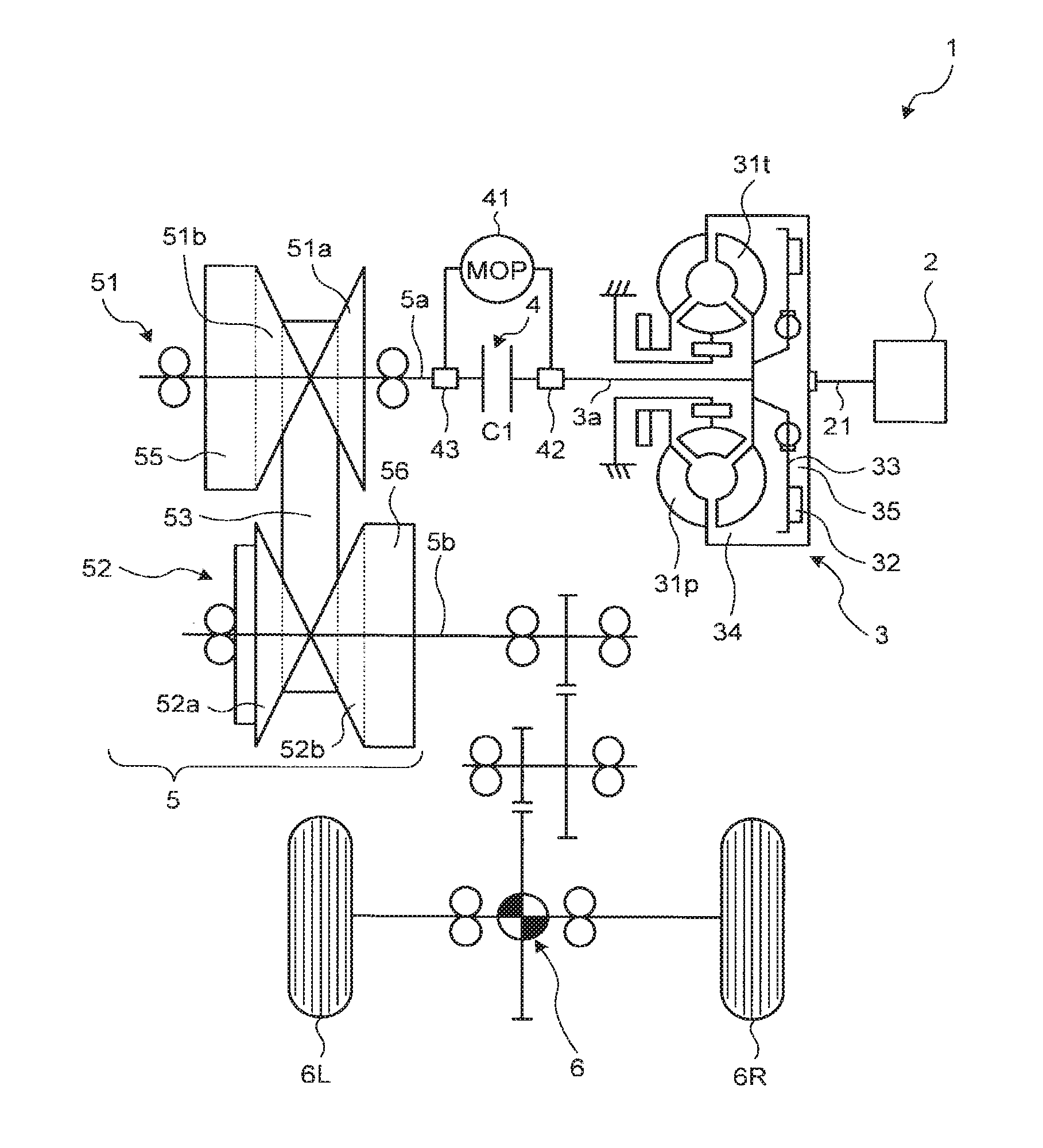
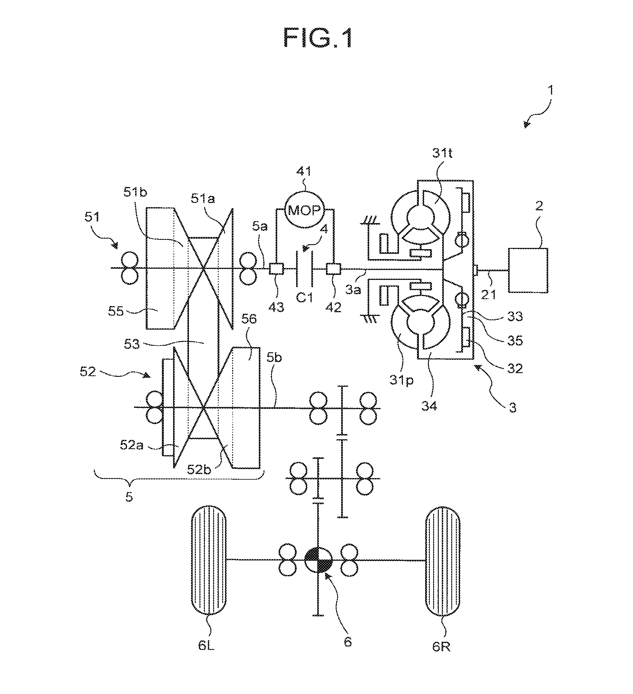
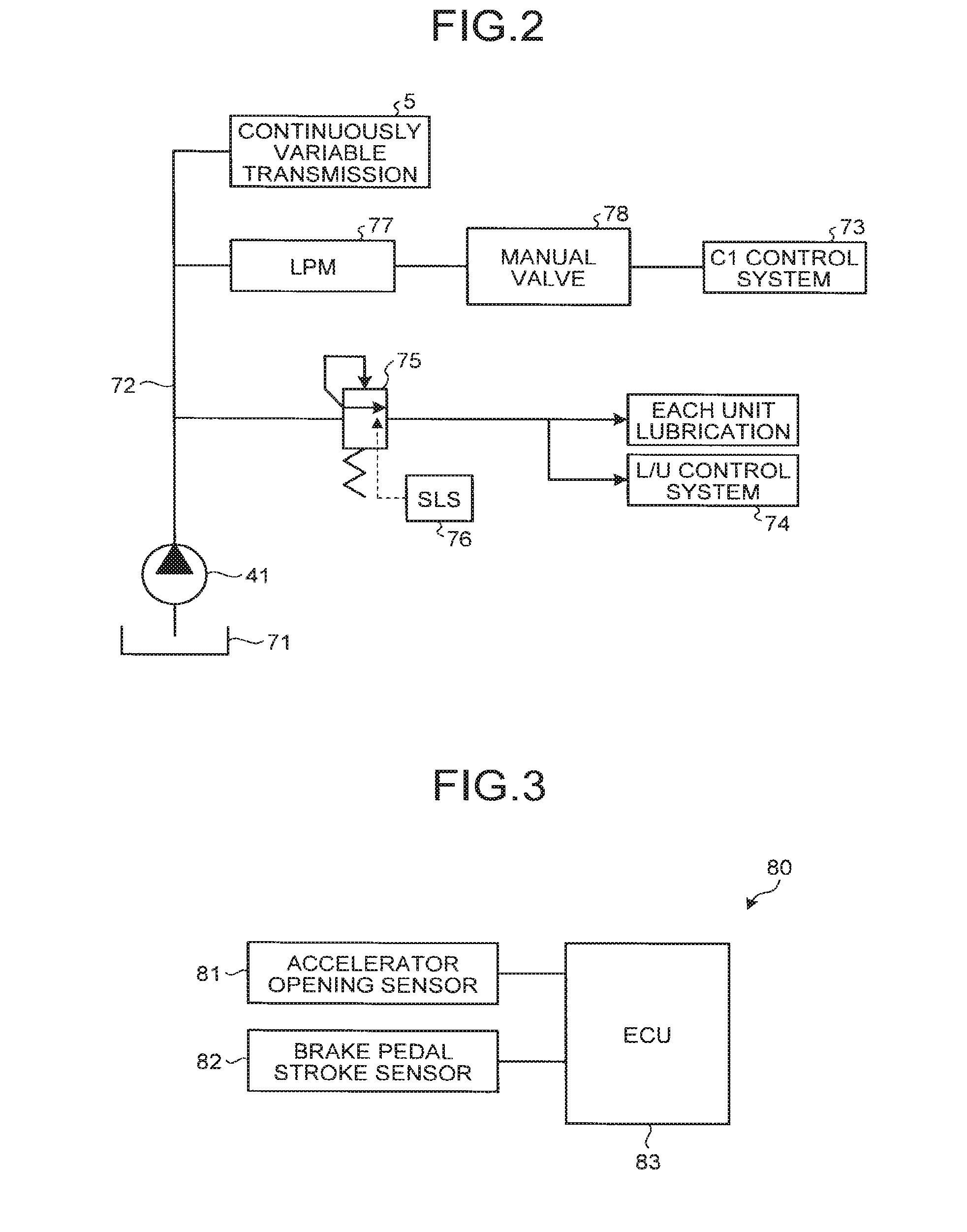
[0043]Operation of a vehicle driving device 80 when a coasting control process being a first embodiment of the present disclosure is executed is first described with reference to FIGS. 4 and 5. FIG. 4 is a flowchart illustrating a flow of the coasting control process being the first embodiment of the present disclosure. FIG. 5 is a timing chart for illustrating the coasting control process being the first embodiment of the present disclosure. Meanwhile, line L1 in FIG. 5(c) indicates a rotational speed Nin on an output side of a C1 clutch 4 and line L2 indicates a rotational speed Ne of an engine 2 and a rotational speed Nt on an input side of the C1 clutch 4.

[0044]The flowchart illustrated in FIG. 4 starts at timing when a vehicle 1 starts traveling and the coasting control process shifts to a process at step S1. The coasting control process is repeatedly executed at each predetermined control cycle while the vehicle 1 runs.

[0045]In the process at step S1, an ECU 83 determines whet...

second embodiment

[0055]Operation of a vehicle driving device 80 when a coasting control process being a second embodiment of the present disclosure is executed is next described with reference to FIGS. 6 and 7. FIG. 6 is a flowchart illustrating a flow of the coasting control process being the second embodiment of the present disclosure. FIG. 7 is a timing chart for illustrating the coasting control process being the second embodiment of the present disclosure. Meanwhile, line L1 in FIG. 7(c) indicates a rotational speed Nin on an output side of a C1 clutch 4 and line L2 indicates a rotational speed Ne of an engine 2 and a rotational speed Nt on an input side of the C1 clutch 4.

[0056]The flowchart illustrated in FIG. 5 starts at timing when a vehicle 1 starts traveling and the coasting control process shifts to a process at step S11. The coasting control process is repeatedly executed at each predetermined control cycle while the vehicle 1 runs.

[0057]In the process at step S11, an ECU 83 determines ...


PUM


Abstract

In a coasting control process, an ECU increases line pressure PL of a hydraulic path to predetermined pressure P1 such that discharge pressure of an MOP becomes higher than that before a C1 clutch is disengaged at timing when an executing condition of coasting control is satisfied (time t=t1). According to such coasting control process, driving torque of the MOP increases, so that deceleration (deceleration G) caused by driving of the MOP by a drive wheel becomes larger than that in conventional coasting control in which the discharge pressure of the MOP is not increased. As a result, it is possible to inhibit a driver from feeling discomfort due to free-running feeling generated during the coasting control.

Description

CROSS-REFERENCE TO RELATED APPLICATION[0001]The present application claims priority to and incorporates by reference the entire contents of Japanese Patent Application No. 2015-021692 filed in Japan on Feb. 6, 2015.BACKGROUND OF THE DISCLOSURE[0002]1. Field of the Disclosure[0003]The present disclosure relates to a vehicle driving device capable of selectively driving a mechanical oil pump by an engine or a drive wheel.[0004]2. Description of the Related Art[0005]A vehicle driving device capable of selectively driving a mechanical oil pump by an engine or a drive wheel is conventionally known. Specifically, Japanese Patent Application Laid-open No. 2011-231844 (refer to paragraph 0027) discloses the vehicle driving device which drives the mechanical oil pump by driving force of the drive wheel during coasting in which a clutch provided on a power transmission path between the engine and the drive wheel is disengaged and the engine stops.[0006]In general, during coasting, the clutch ...

Claims


Application Information

Patent Timeline
IPC IPC(8): F16D48/02
CPCF16D48/02F16D2048/0227F16D2500/3108B60Y2300/18083B60W30/18072B60Y2300/42F16H61/662B60Y2400/427F16H2059/186F16H61/0028F16H61/0021B60W10/02B60W10/06B60W2710/022B60W2710/0616B60W2540/12B60W2540/10B60W2030/1809B60W2710/1088B60W10/107B60W10/30Y02T10/40Y02T10/60
Inventor MORINO, TAKUROITO, YOSHIOYANAGIDA, TOMOAKIKIMURA, KENTANAGASATO, YUHIRATA, TAKUYAOSADA, TOMOE
Owner TOYOTA JIDOSHA KK
Why Eureka
Try Eureka