
Structure of curved liquid crystal panel

a liquid crystal panel and curved technology, applied in non-linear optics, instruments, optics, etc., can solve the problems of irregular liquid crystal display, poor ability to display at the edges of the screen, and differences in light transmittance and response time between the central portion and the opposite side edge portions, so as to enhance the optical taste of the curved liquid crystal panel and light transmittance

Inactive Publication Date: 2016-08-11
SHENZHEN CHINA STAR OPTOELECTRONICS TECH CO LTD
View PDF4 Cites 20 Cited by
  • Summary
  • Abstract
  • Description
  • Claims
  • Application Information

AI Technical Summary

Benefits of technology

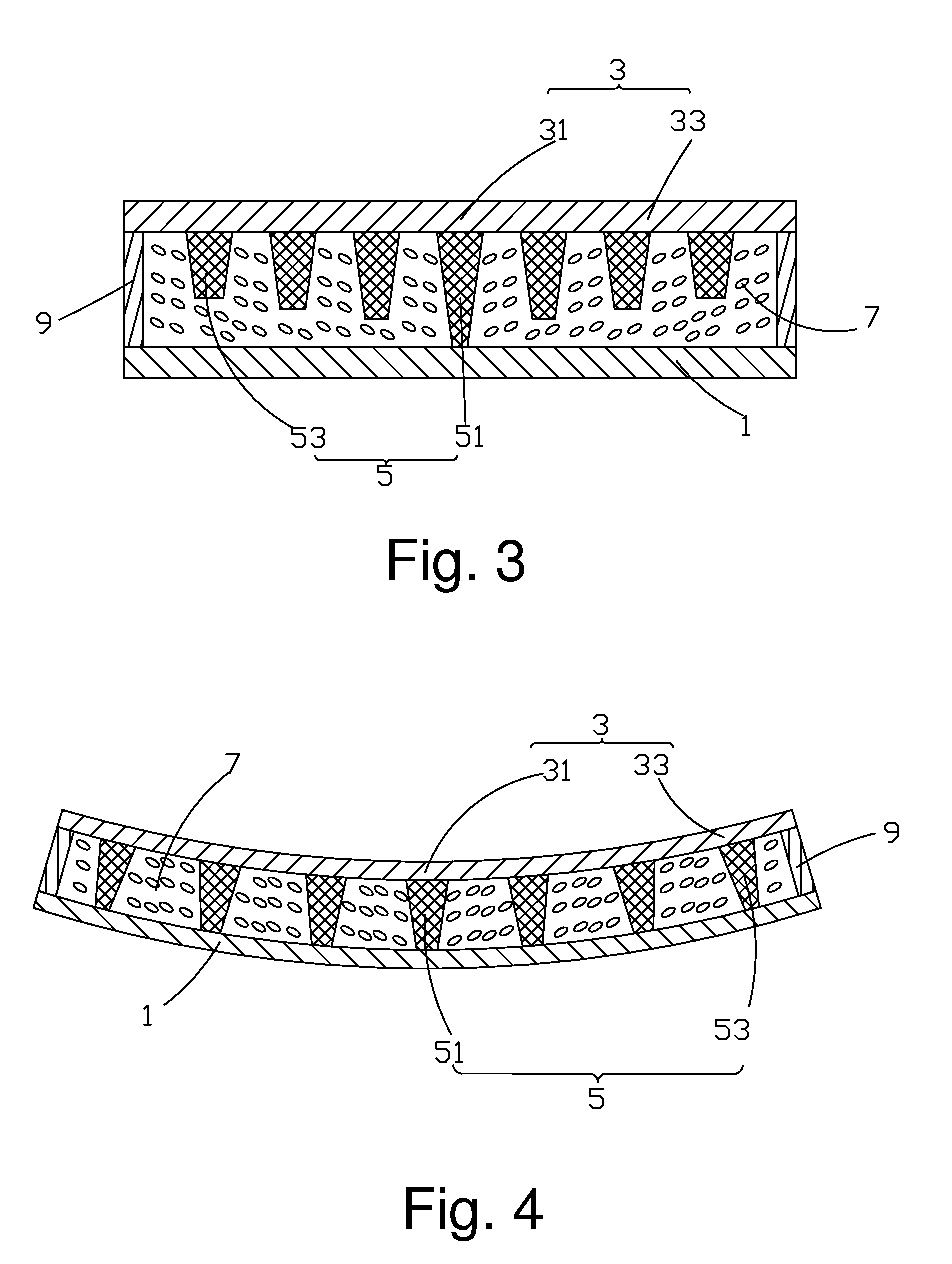
The present invention provides a curved liquid crystal panel with a uniform cell thickness and a consistent distribution of thickness of the liquid crystal layer, which enhances the optical taste and makes light transittance and response time consistent. This is achieved by using an arrangement with greater heights or density of spacers located in the middle zone compared to those of the side edge zones, which leads to greater stress on the middle zone spacers. This results in a constant distance between the CF substrate and the TFT substrate, improving the overall quality of the curved liquid crystal panel. The structure of the invention is simple and easy to achieve.

Problems solved by technology

Generally speaking, the curved liquid crystal displays allow for the best viewing effect from edge to edge, while a regular liquid crystal display has poor capability of displaying at edges of a screen.
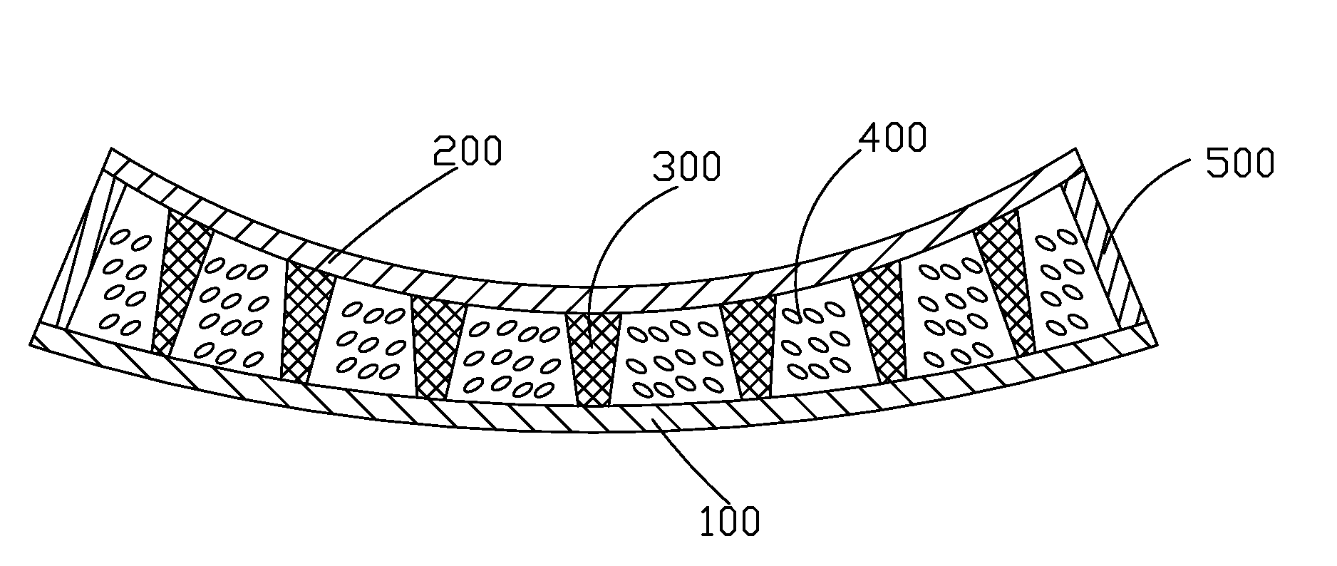
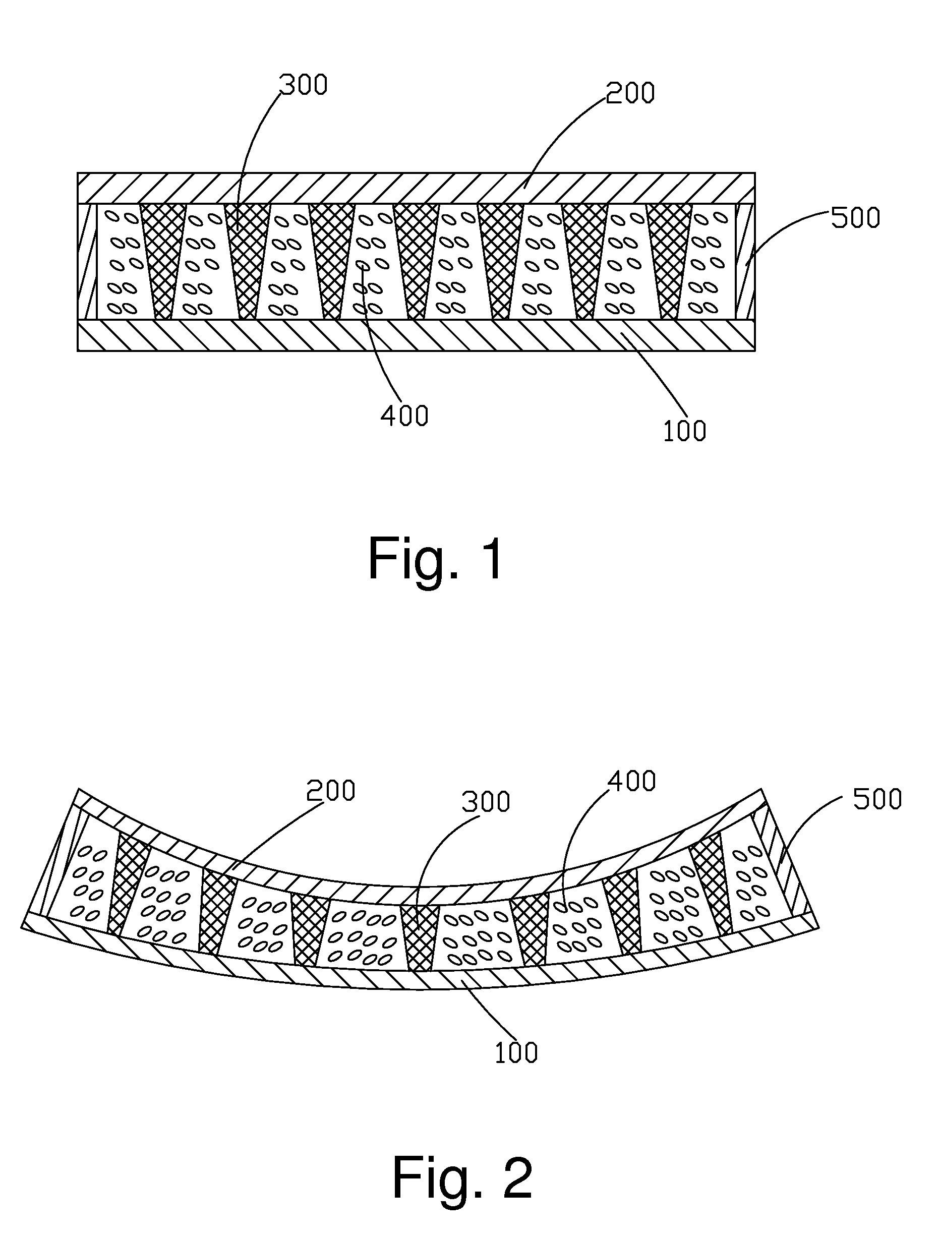
However, the spacers 300 are arranged in such a manner as to be of identical heights, density, and CD values and this results in a greater deformation in the central portion of the curved liquid crystal panel than those of the two opposite side edge portions, so that the cell thickness of the central portion is less than the cell thickness of the two side edge portions, leading to non-uniform distribution of the thickness of the liquid crystal layer and differences of light transmittance and response time between the central portion and the opposite side edge portions.
Eventually, burring of the display images of the curved liquid crystal panel may result and the optical taste deteriorates.

Method used


Image

  • Structure of curved liquid crystal panel
  • Structure of curved liquid crystal panel
  • Structure of curved liquid crystal panel

Examples


Embodiment Construction

[0034]To further expound the technical solution adopted in the present invention and the advantages thereof, a detailed description is given to a preferred embodiment of the present invention and the attached drawings.

[0035]Referring to FIGS. 3 and 4, a structure of a curved liquid crystal panel according to a first preferred embodiment of the present invention is shown. The curved liquid crystal panel structure comprises: a TFT (Thin-Film Transistor) substrate 1, a CF (Color Filter) substrate 3 opposite to the TFT substrate 1, spacers 5 arranged between the TFT substrate 1 and the CF substrate 3, a liquid crystal layer 7 disposed between the TFT substrate 1 and the CF substrate 3, and an enclosing sealant layer 9 arranged between and located along a periphery of the TFT substrate 1 and the CF substrate 3. The TFT substrate 1 is provided to drive liquid crystal molecules contained in the liquid crystal layer 7 to rotate in order to carry out selection of light transmitting through t...


PUM


Abstract

The present invention provides a structure of a liquid crystal panel, which includes a TFT substrate (1), a CF substrate (3) opposite to the TFT substrate (1), spacers (5) arranged between the TFT substrate (1) and the CF substrate (3), a liquid crystal layer (7) disposed between the TFT substrate (1) and the CF substrate (3), and an enclosing sealant layer (9) arranged between and located along a periphery of the TFT substrate (1) and the CF substrate (3). In a curving direction of the curved liquid crystal panel, the CF substrate (3) includes middle zone (31) and two side edge zones (33) at two opposite sides of the middle zone. The middle zone (31) bears a stress greater than stresses born by the two side edge zones (33). The spacers (51) that are located in the middle zone (31) are arranged to bear a stress that is greater than stresses born by the spacers (53) that are located in the two side edge zones (33) so as to maintain a constant distance between the CF substrate (3) and the TFT substrate (1) and achieve the consistency of cell thickness in the entirety of the curved liquid crystal panel.

Description

BACKGROUND OF THE INVENTION[0001]1. Field of the Invention[0002]The present invention relates to the field of liquid crystal displaying, and in particular to a structure of a curved liquid crystal panel.[0003]2. The Related Arts[0004]Liquid crystal displays (LCDs) have a variety of advantages, such as thin device body, low power consumption, and being free of radiation, and are thus of wide applications, such as liquid crystal televisions, mobile phones, personal digital assistants (PDAs), digital cameras, computer monitors, and notebook computer screens.[0005]A liquid crystal display generally comprises an enclosure, a liquid crystal panel arranged in the enclosure, and a backlight module mounted in the enclosure. The liquid crystal panel has a structure that is generally composed of a thin-film transistor (TFT) array substrate, a color filter (CF) substrate, and a liquid crystal layer arranged between the two substrates and the principle thereof is that a driving voltage is applie...

Claims


Application Information

Patent Timeline
IPC IPC(8): G02F1/1339G02F1/1335G02F1/1368
CPCG02F1/1339G02F1/133514G02F2001/13396G02F1/1368G02F1/13394G02F1/133305G02F1/13396
Inventor WU, CHUANGUO, JINBOLO, SHIHHSUN
Owner SHENZHEN CHINA STAR OPTOELECTRONICS TECH CO LTD
Learn More