Conductive sheet, touch panel device, display device, and method for manufacturing conductive sheet

a technology of touch panel and conductive sheet, which is applied in the direction of electric digital data processing, instruments, computing, etc., can solve the problems of reducing the visibility of images displayed on the display surface disposed below the touch panel, and achieve the effect of good visibility of displayed images

Inactive Publication Date: 2016-08-11
SHARP KK
View PDF4 Cites 22 Cited by
  • Summary
  • Abstract
  • Description
  • Claims
  • Application Information

AI Technical Summary

Benefits of technology

[0016]According to the present invention, it is possible to realize: a conductive sheet that, even when disposed on a display surface of a liquid crystal display device or the like, appropriately prevents interference and ensures good visibility of displayed images; a touch panel device; a display device; and a method of manufacturing the conductive sheet.

Problems solved by technology

As a result, there are instances in which the metal wiring lines become visible when the wiring lines are not evenly distributed on the touch panel surface, thereby leading to a marked decrease in the visibility of images displayed on a display surface disposed below the touch panel.

Method used


Image

  • Conductive sheet, touch panel device, display device, and method for manufacturing conductive sheet
  • Conductive sheet, touch panel device, display device, and method for manufacturing conductive sheet
  • Conductive sheet, touch panel device, display device, and method for manufacturing conductive sheet

Examples


embodiment 1

[0034]Embodiment 1 is described below with reference to the drawings.

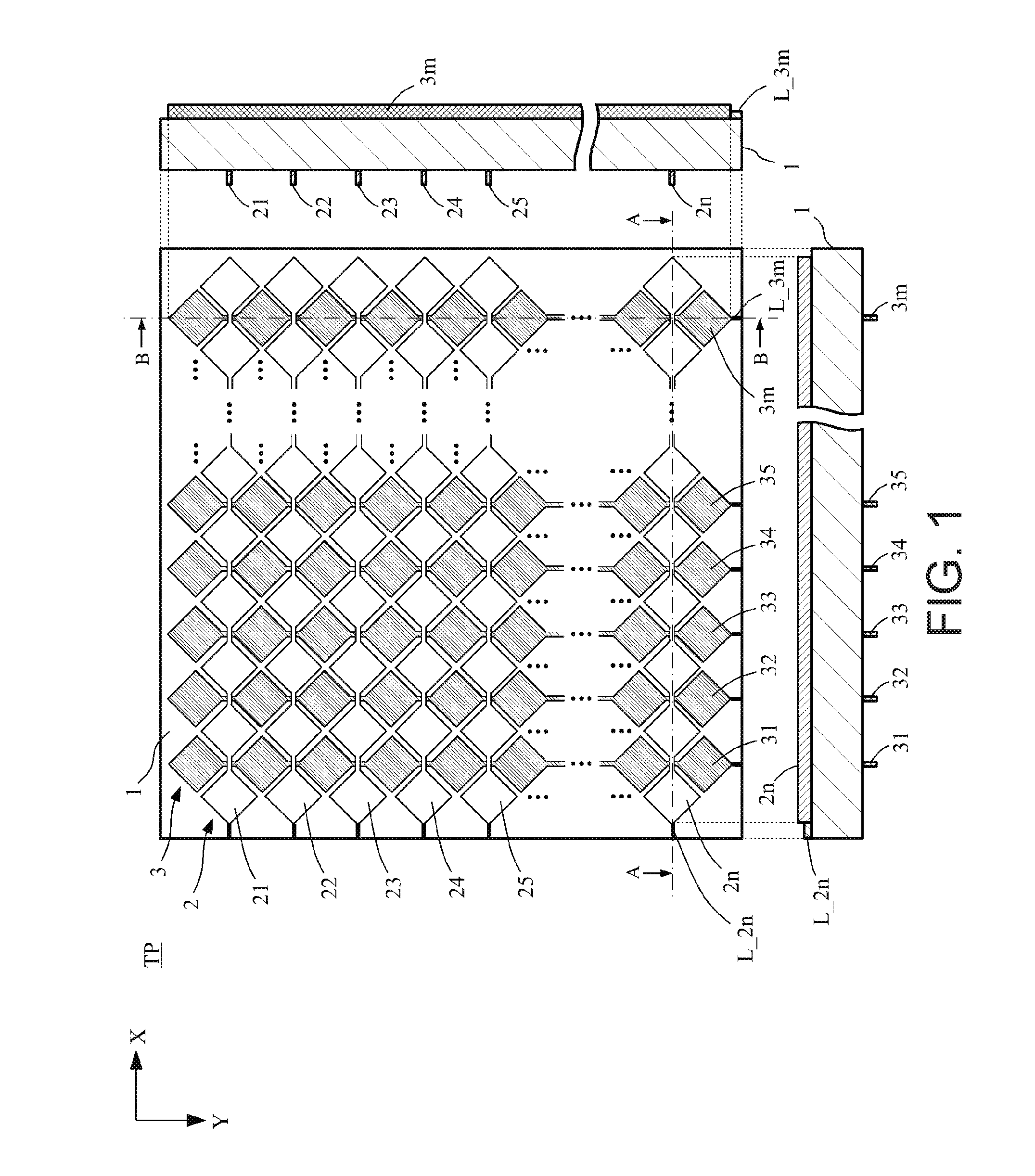
[0035]FIG. 1 is a schematic configuration diagram of a touch panel TP that is one example of a conductive sheet according to Embodiment 1. Specifically, FIG. 1 shows a plan view of the touch panel TP, a cross-sectional view A-A (bottom of the figure), and a cross-sectional view B-B (right side of the figure).

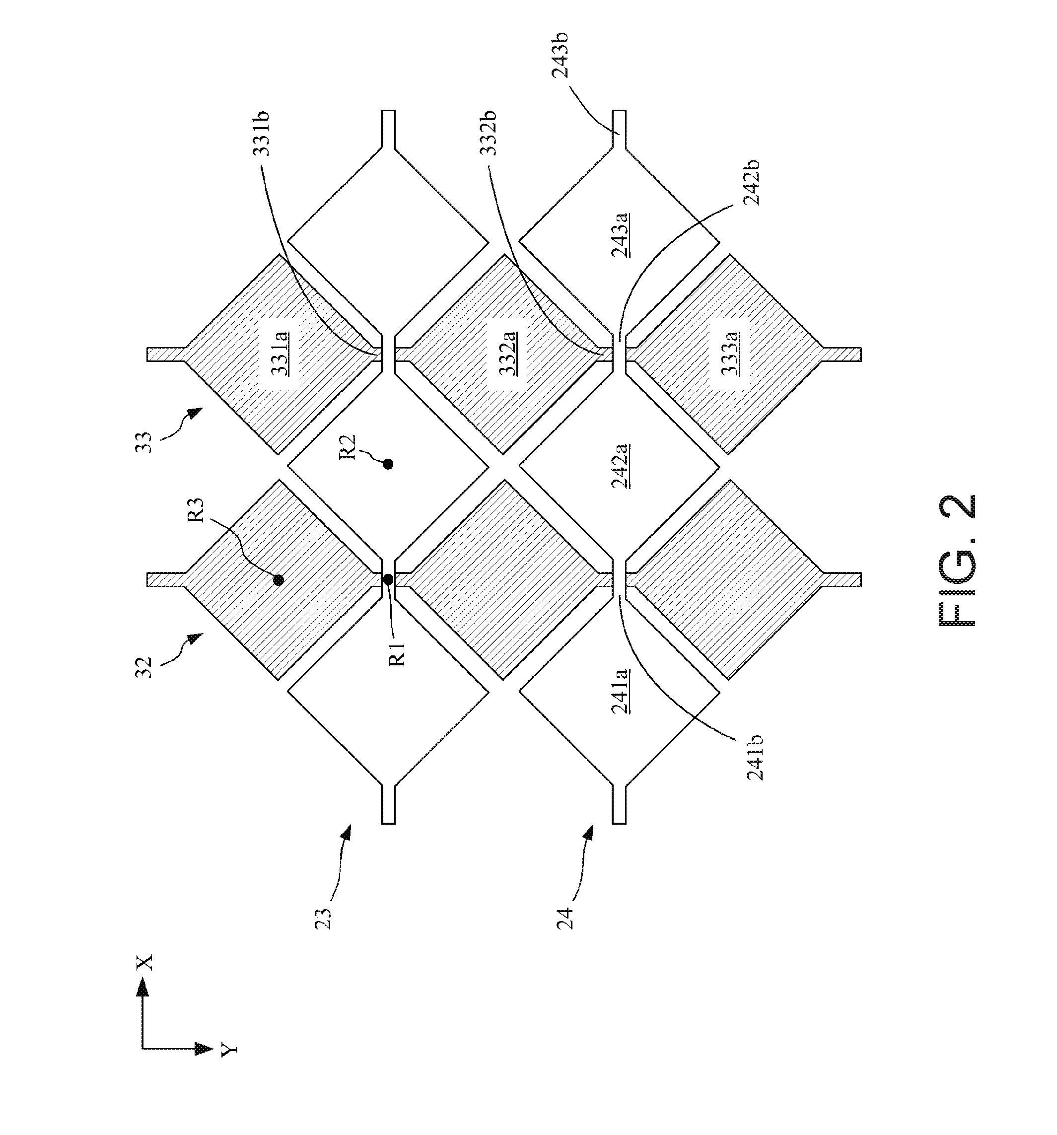
[0036]FIG. 2 enlarges a region that is a portion of the touch panel TP of FIG. 1 in a plan view.

[0037]As shown in FIGS. 1 and 2, the X axis and Y axis are set in FIGS. 1 and 2.

[0038]As shown in FIG. 1, the touch panel TP includes: the substrate 1; the X axis direction electrode part 2 formed on the first main surface of the substrate 1; and the Y axis direction electrode part 3 formed on the second main surface of the substrate 1.

[0039]The first substrate 1 has insulating properties and is formed via a material that has high light transmittance (a colorless transparent resin, glass, plastic, PET (polyethylene t...

embodiment 2

[0099]Next, Embodiment 2 will be described.

[0100]Below, parts particular to the present embodiment will be described, and a detailed description of the parts similar to the embodiment described above will be omitted.

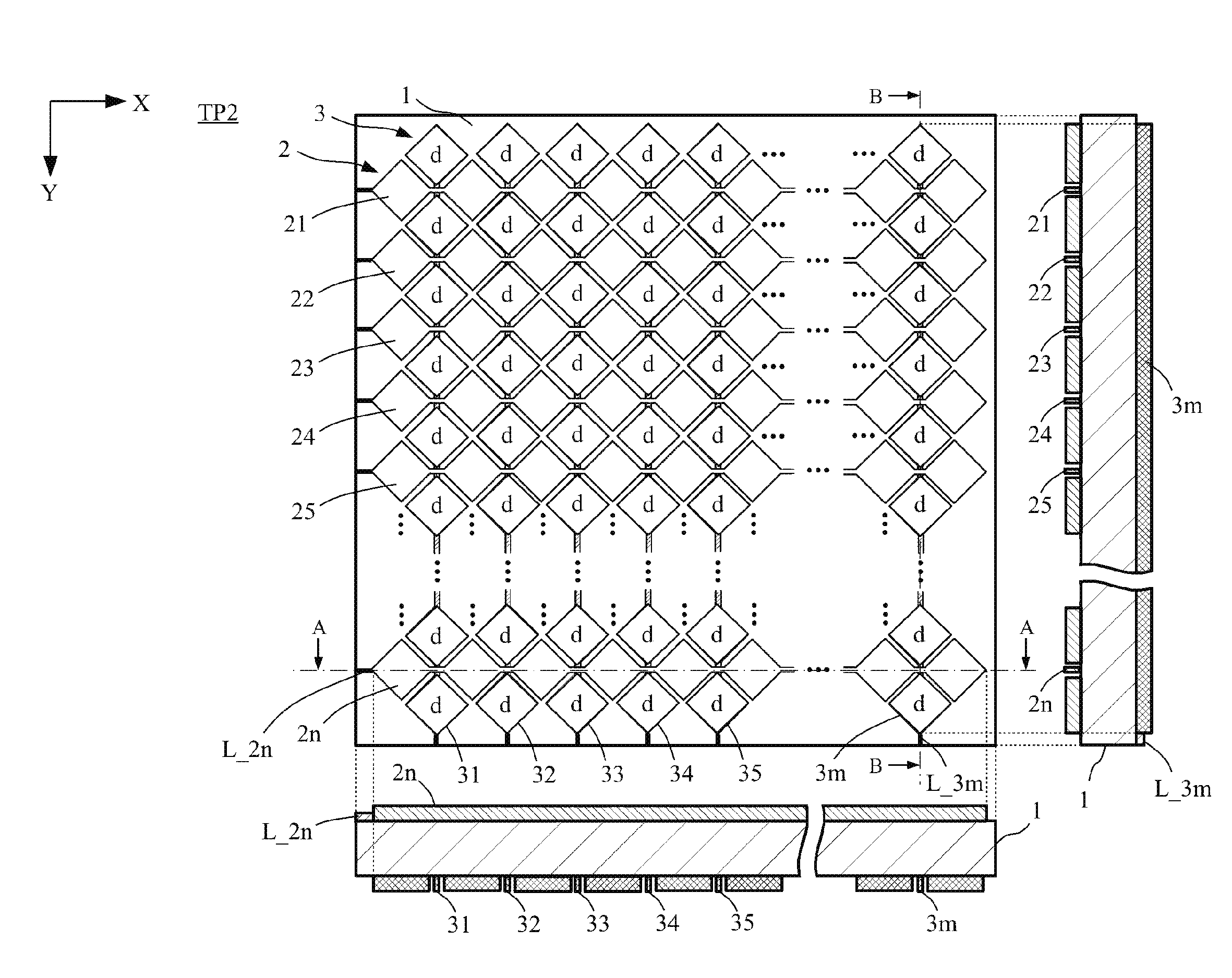
[0101]FIG. 12 is a schematic configuration diagram of a touch panel TP2 (one example of a conductive sheet) according to Embodiment 2. Specifically, FIG. 12 shows a plan view of the touch panel TP, a cross-sectional view A-A (bottom of the figure), and a cross-sectional view B-B (right side of the figure).

[0102]The touch panel TP2 of the present embodiment has a configuration in which, in the touch panel TP of Embodiment 1: (1) dummy electrodes (the diamond-shaped electrodes with a “d” in FIG. 12) are provided in regions that overlap in a plan view the electrodes of the Y axis direction electrode part 3 on the first main surface of the substrate 1; and (2) in which dummy electrodes are further provided in regions that overlap the electrodes of the X axis direction electr...


PUM

PropertyMeasurementUnit
widthaaaaaaaaaa
wire width Wxaaaaaaaaaa
width Wx1aaaaaaaaaa

Abstract

A touch panel includes: a substrate; an X axis direction electrode part; and a Y axis direction electrode part. The X axis direction electrode part includes a plurality of fine metal wires formed on one main surface (a first main surface) of the substrate. The Y axis direction electrode part includes a plurality of fine metal wires formed on another main surface (a second main surface) of the substrate. In bridge regions in which the X axis direction electrode part and the Y axis direction electrode part overlap in a plan view, the wiring pattern of the plurality of the fine metal wires included in the X axis direction electrode part is identical to the wiring pattern of the plurality of the fine metal wires included in the Y axis direction electrode part. In the bridge regions, the wire width of the fine metal wires included in the X axis direction electrode part is larger than the wire width of the fine metal wires included in the Y axis direction electrode part.

Description

TECHNICAL FIELD[0001]The present invention relates to a touch panel device and a conductive sheet used in touch panel devices and the like.BACKGROUND ART[0002]A touch panel device is a device in which information can be input into the device via a finger or pen contacting the touch panel surface. In recent years, capacitive touch panel devices, which have good detection sensitivity and excellent operability, have been used in various types of devices. In particular, projection-type capacitive touch panel devices, which can accurately detect the coordinates at which a finger or pen contacts the touch panel surface, are widely used.[0003]Projection-type capacitive touch panel devices include a plurality of drive lines and a plurality of sense lines. A plurality of X axis direction sense electrodes are provided on the respective drive lines, and a plurality of Y axis direction sense electrodes are provided on the respective sense lines. In a projection-type capacitive touch panel devic...

Claims


Application Information

Patent Timeline
Patent Type & Authority Applications(United States)
IPC IPC(8): G06F3/041G06F3/044
CPCG06F3/044G06F2203/04103G06F2203/04112G06F3/0418G06F2203/04111G06F3/0445G06F3/0446
Inventor NAGATA, KOSUKEHATA, MASAYUKINOMA, MIKIHIRO
Owner SHARP KK
Why Eureka
Try Eureka