System and Method for Visualization of a Mechanical Integrity Program

a technology of mechanical integrity and system, applied in the field of mechanical integrity programs, can solve the problems of time-consuming and laborious processing and representation, difficult and expensive to further analyze and visualize the as-built structure and their respective statuses, etc., and achieve the effect of reducing labor and improving efficiency and effectiveness of mechanical integrity programs

Active Publication Date: 2016-08-11
HAAG ENG
View PDF0 Cites 4 Cited by
  • Summary
  • Abstract
  • Description
  • Claims
  • Application Information

AI Technical Summary

Benefits of technology

[0004]It would be advantageous to fully analyze and visualize facilities, products, processes, and systems before the facility is fully constructed, or after as an as-built facility. It would also be desirable to enable a computer-based solution that would improve efficiency and effectiveness of mechanical integrity programs while reducing labor. To better address one or more of these concerns, a system and method for visualization of mechanical integrity programs is disclosed that applies various engineering disciplines associated with the design, assurance, and verification functions that ensure a facility during construction or an as-built facility, for example, meets its appropriate and intended requirements.

Problems solved by technology

Despite the importance of monitoring, processing and representation are time-consuming and labor-intensive.
In particular, existing techniques make it difficult and expensive to further analyze and visualize the as-built structures and their respective statuses.

Method used


Image

  • System and Method for Visualization of a Mechanical Integrity Program
  • System and Method for Visualization of a Mechanical Integrity Program
  • System and Method for Visualization of a Mechanical Integrity Program

Examples


Embodiment Construction

[0013]While the making and using of various embodiments of the present invention are discussed in detail below, it should be appreciated that the present invention provides many applicable inventive concepts, which can be embodied in a wide variety of specific contexts. The specific embodiments discussed herein are merely illustrative of specific ways to make and use the invention, and do not delimit the scope of the present invention.

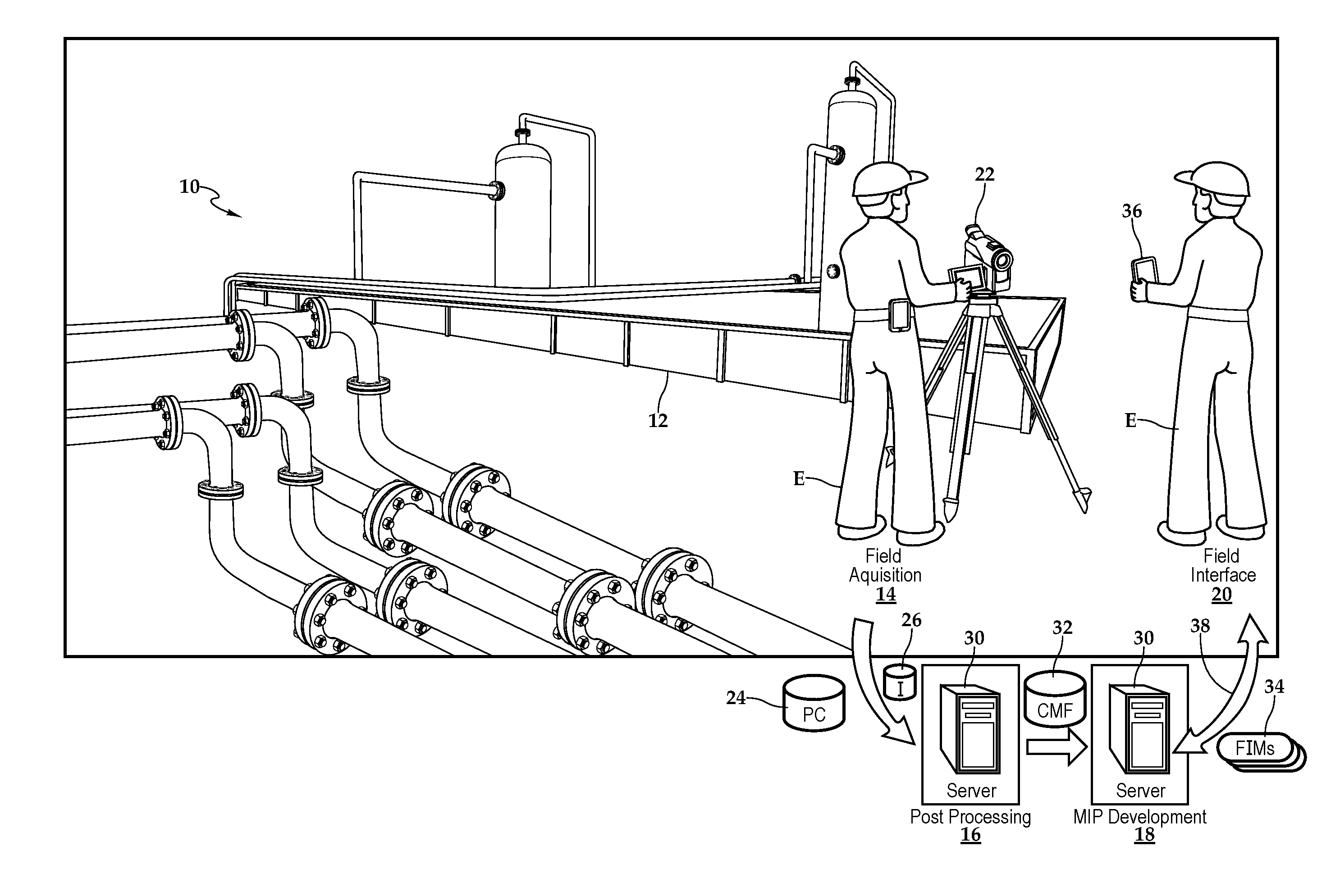
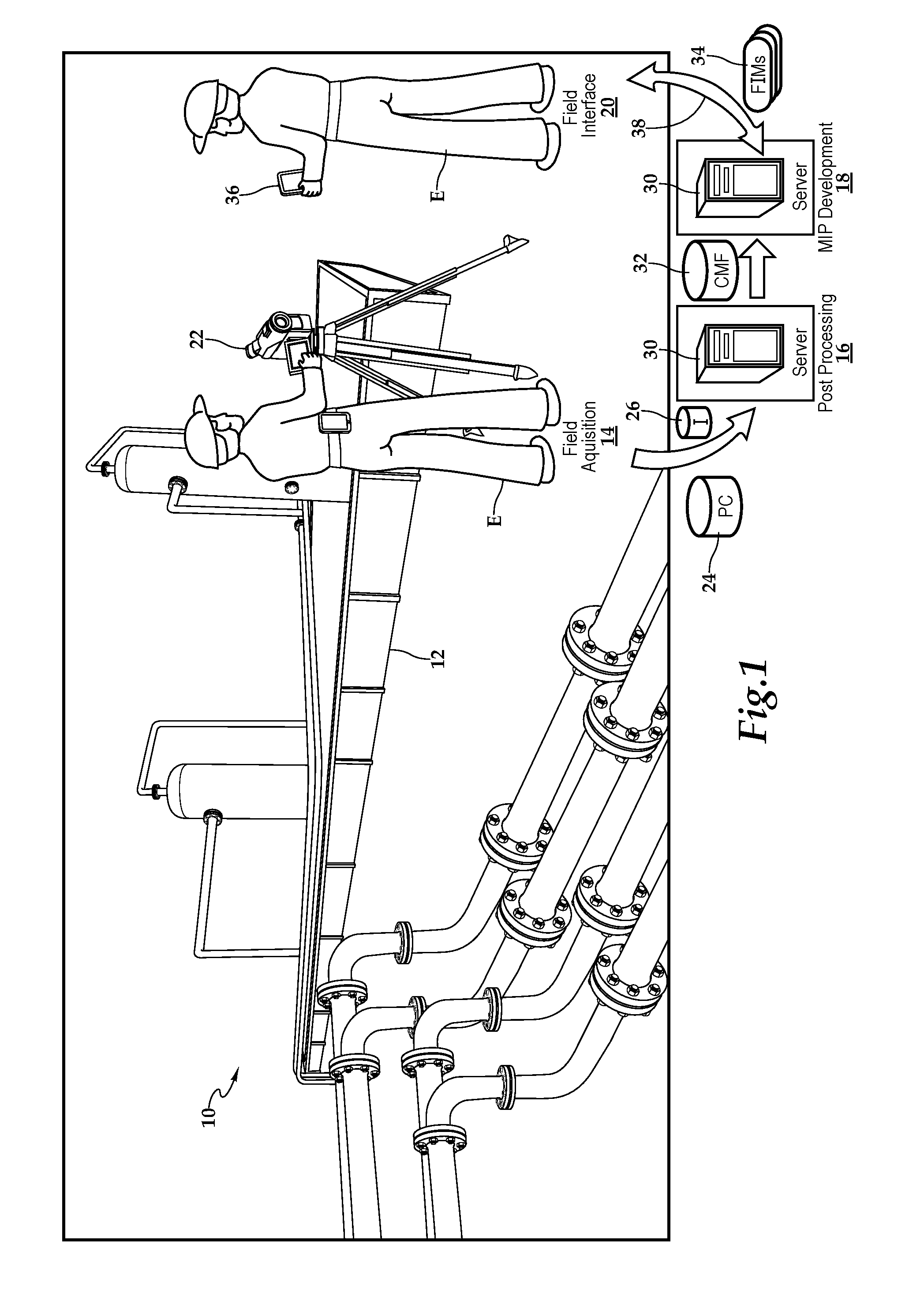
[0014]Referring initially to FIG. 1, therein is depicted one embodiment of a system for visualization of mechanical integrity programs that is schematically illustrated and designated 10. The system 10 is being utilized at an as-built site, which is depicted as oil field production site 12. At this oil field production site 12, a mechanical integrity program is being implemented that provides design, assurance, and verification functions that ensure the as-built site meets appropriate and intended requirements. It should be appreciated that although FI...


PUM


Abstract

A system and method for visualization of a mechanical integrity program are disclosed. In one embodiment, a mechanical integrity program server is configured to provide design, assurance, and verification functions that ensure a site, or a site under development, meets appropriate and intended requirements. Based on point cloud data and digital imagery collected from the site, a composite model file is built. Operational elements, interconnection of the operational elements, and instrumentation of the site are identified within the composite model file. Responsive to user input, a mechanical integrity program is generated including processes for assuring the site is in satisfactory condition to safely and reliably perform its intended purpose. Various field interface modes for viewing on a programmable interactive device permit field inspection of the site, which may be an as-built site or a site under development.

Description

PRIORITY STATEMENT & CROSS-REFERENCE TO RELATED APPLICATIONS[0001]This application claims priority from U.S. Patent Application No. 62 / 114,037 entitled “System and Method for Visualization of a Mechanical Integrity Program” filed on Feb. 9, 2015, which is hereby incorporated by reference for all purposes.TECHNICAL FIELD OF THE INVENTION[0002]This invention relates, in general, to mechanical integrity programs and, in particular to systems and methods for visualization of mechanical integrity programs that applies various engineering disciplines associated with the design, assurance, and verification functions that ensure a facility meets its appropriate and intended requirements.BACKGROUND OF THE INVENTION[0003]Accurate and efficient tracking of proposed or as-built structures and the accompanying actual statuses has been repeatedly reported as a critical factor for the success of project control, including construction oversight and operations and maintenance. Despite the importanc...

Claims


Application Information

Patent Timeline
Patent Type & Authority Applications(United States)
IPC IPC(8): G06F17/50
CPCG06F17/5086G06F30/17
Inventor ZMIJEWSKI, CHRISTOPHER M.
Owner HAAG ENG
Why Eureka
Try Eureka