Skull implant type medication injection port

a technology of injection port and scalp, which is applied in the direction of medical devices, intravenous devices, medical devices, etc., can solve the problems of difficult to sense the effect of scalp touch, low strength, complicated procedure, etc., and achieve the effect of easy identification

Active Publication Date: 2016-08-18
NAT CANCER CENT
View PDF5 Cites 4 Cited by
  • Summary
  • Abstract
  • Description
  • Claims
  • Application Information

AI Technical Summary

Benefits of technology

[0011]A skull implant type medication injection port in accordance with one embodiment of the present invention includes a mounted portion and a medication storage portion which has a predetermined height ratio based on a rib, thereby making it possible for the skull implant type injection port to be appropriately implanted into a port insertion hole formed in a cranium and be easily identified after implanting the skull implant type injection port.
[0012]Also, a skull implant type medication injection system in accordance with one embodiment of the present invention includes a guide needle, thereby simply and precisely being able to perform an implantation of the skull implant type medication injection port.[

Problems solved by technology

However, since conventional body-implanted medication injection ports do not have structures suitable for being inserted into a patient's cranium during a procedure for anticancer medication treatment for a brain tumor patient, the procedure is complicated and an implanted portion remains externally protruded after the procedure.
However, since a storage portion in the technology is formed of a plastic material, the strength thereof is low and it is difficult to sense it via touch under the scalp.
Particularly, when medication is repeatedly injected, the medication frequently leaks under the scalp due to the weak material membrane of an upper hemisphere of the storage portion.

Method used


Image

  • Skull implant type medication injection port
  • Skull implant type medication injection port
  • Skull implant type medication injection port

Examples


Embodiment Construction

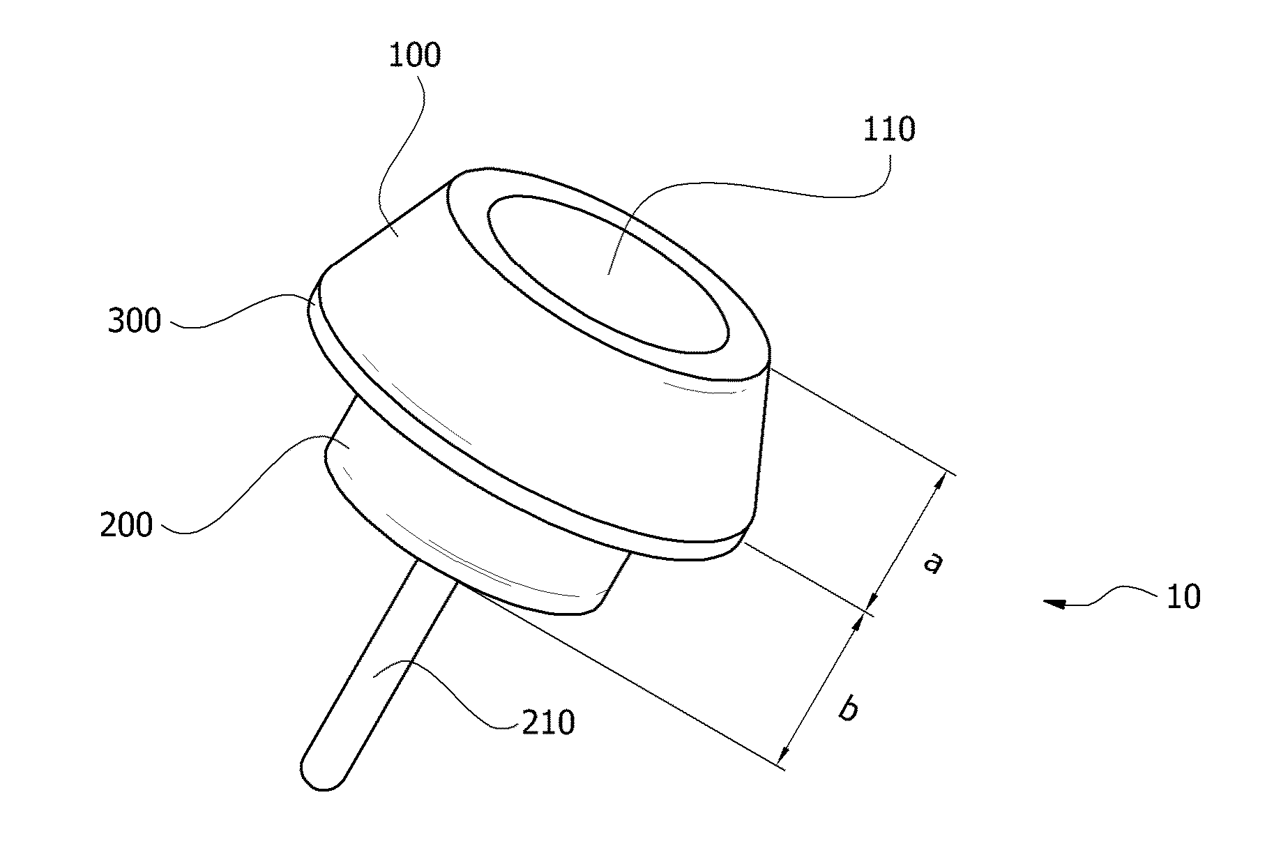
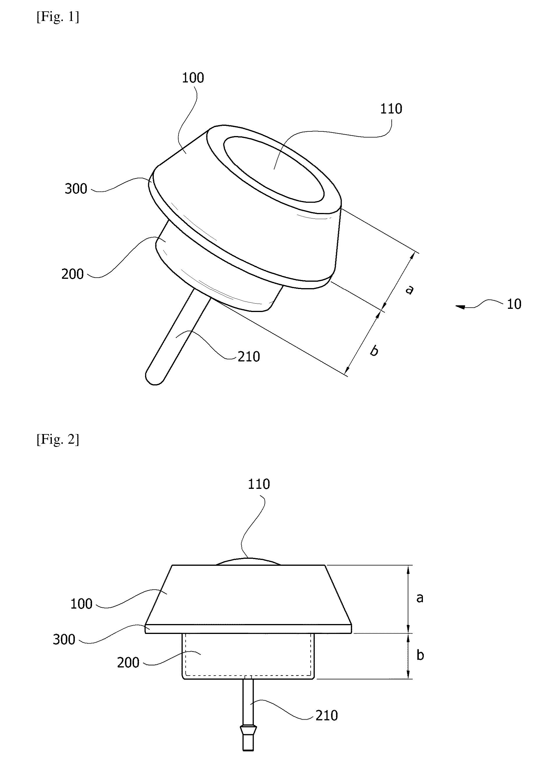
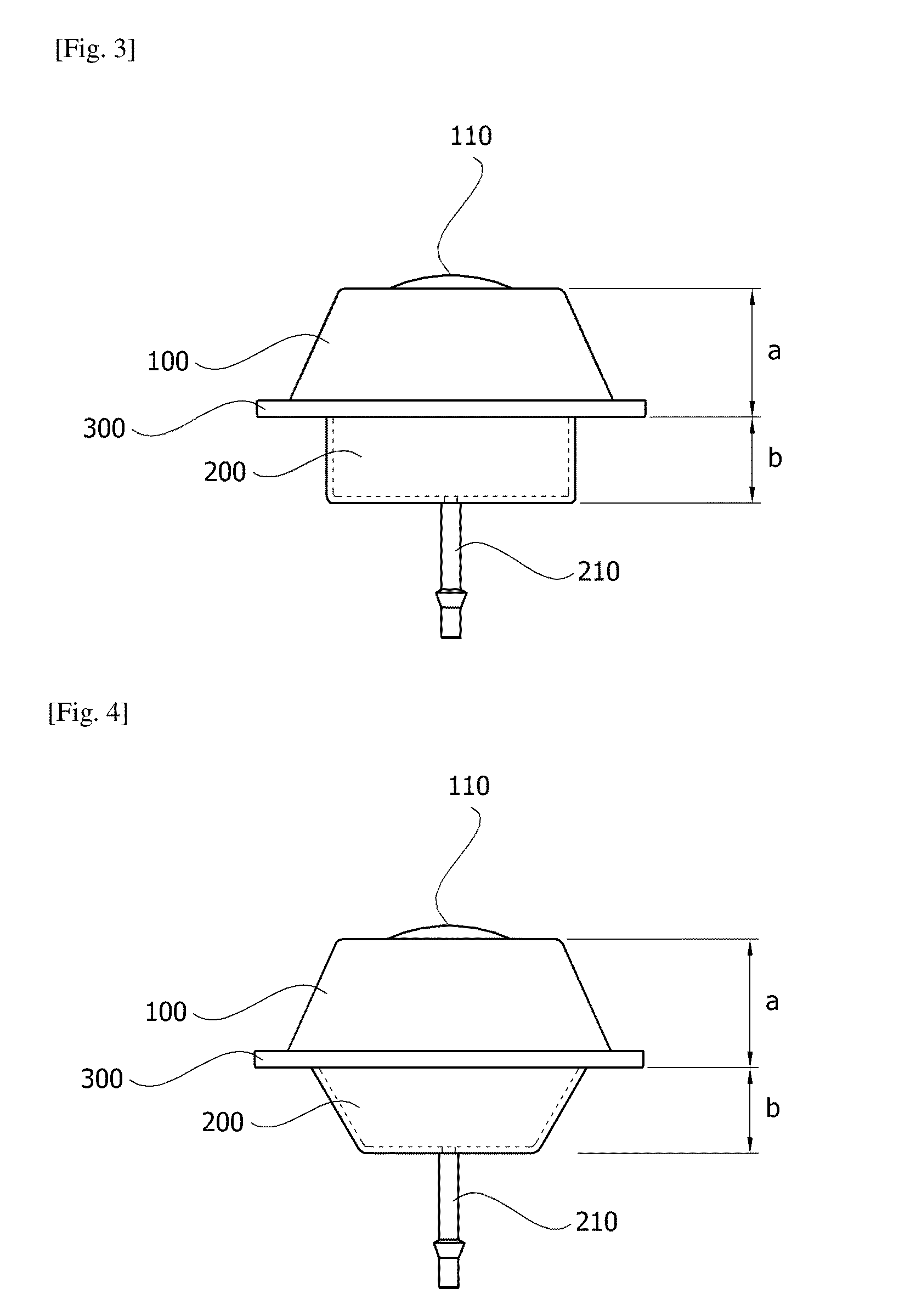
[0024]The present invention relates to a skull implant type medication injection port including a mounted portion which is placed on the upper section of a port insertion hole formed in a patient's cranium and comprises a medication inlet formed on a top surface, a medication injection diaphragm configured to seal the medication inlet of the mounted portion into which an injection needle for injecting a medication is inserted, a medication storage portion which is coupled with a bottom of the mounted portion and stores the medication injected through the medication injection diaphragm, a medication discharge pipe connected to the medication storage portion to discharge the medication stored in the medication storage portion, and a rib which is formed on a perimeter between the mounted portion and the medication storage portion and has a diameter greater than an inner diameter of the port insertion hole. Here, a height ratio of the mounted portion to the medication storage portion ba...


PUM


Abstract

A skull implant medication injection port comprises: a mounted portion placed on an upper section of a port insertion hole in a patient's cranium and a medication inlet on a top surface; a medication injection diaphragm that seals the medication inlet of the mounted portion where a needle for injecting a medication is inserted; a medication storage portion coupled with a bottom of the mounted portion stores the medication injected through the medication injection diaphragm; a medication discharge pipe connected to the medication storage portion discharges the medication stored in the medication storage portion; and a rib formed on a perimeter between the mounted portion and the medication storage portion that has a diameter larger than an inner diameter of the port insertion hole. A height of the mounted portion is generally about 4 to 7 mm, and a height of the medication storage portion is generally about 2 to 4.2 mm.

Description

TECHNICAL FIELD[0001]The present invention relates to a skull implant type medication injection port capable of discharging a medication injected from the outside of a human body into a human body through a medication discharge pipe.BACKGROUND ART[0002]Generally, a body-implanted medication injection port is a device developed for a patient who suffers from an illness which requires constant performance of continuous or intermittent medication injections over a long period, and a body-implanted medication injection port is capable of discharging a medication injected from the outside to a desired part through a medication discharge pipe while remaining implanted in patient's body.[0003]A cancer patient is a patient who requires constantly performance of continuous or intermittent medication injections. In addition to a periodic injection of anticancer medication for treatment, 50% of all cancer patients require additional injections of painkillers for reducing pain.[0004]Body-implan...

Claims


Application Information

Patent Timeline
Patent Type & Authority Applications(United States)
IPC IPC(8): A61M39/02
CPCA61M39/0208A61M39/0247A61M2039/0223A61M2039/0205A61M2039/0276A61M2039/0282A61M2039/025A61M5/14A61M5/46
Inventor LEE, SEUNG HOONGWAK, HO-SHINKIM, KWANG GISHIN, SANG-HOONYOO, HEONLEE, JIN SOO
Owner NAT CANCER CENT
Why Eureka
Try Eureka