
Turbocharger system for an engine

Active Publication Date: 2016-08-18
CATERPILLAR INC
View PDF8 Cites 2 Cited by
  • Summary
  • Abstract
  • Description
  • Claims
  • Application Information

AI Technical Summary

Benefits of technology

The present invention provides a system with two turbochargers for an engine. The system includes a first valve assembly that selectively bypasses exhaust from the engine to the low pressure turbocharger, and a storage tank containing a pressurized fluid that is used by both turbochargers. The system also includes a controller that selectively operates the first and second valve assemblies based on the engine's load requirements. The technical effect is improved engine performance and efficiency with optimized turbocharger usage and load control.

Problems solved by technology

In some cases, a response to external loads by an engine of these rig applications may be sluggish, when the engine runs on natural gas.
However, there may be a lag from turbochargers in responding to different power demands thereby effecting response of the engine to power demands.
Such a sluggish response from the engines can negatively affect operations.
In rig applications, operations are intermittent and it is difficult and / or expensive to maintain the engines at a constant heavy loading.
However, it is not cost effective to provide full load all the time, as engines bum fuel to generate power.
The turbochargers in series can provide enough airflow for the full load operating conditions but tend to lack air flow for part load conditions.
In some situations, with multiple engines and associated turbochargers, a rig control system may operate one engine at a full load, and may slightly reduce a power output for rest of the engines.
However, these engines still may have to run at relatively high load conditions to minimize the turbocharger lag.
However, the '378 reference does not disclose a system for operation of multiple turbochargers connected in series.

Method used


Image

  • Turbocharger system for an engine
  • Turbocharger system for an engine
  • Turbocharger system for an engine

Examples


Embodiment Construction

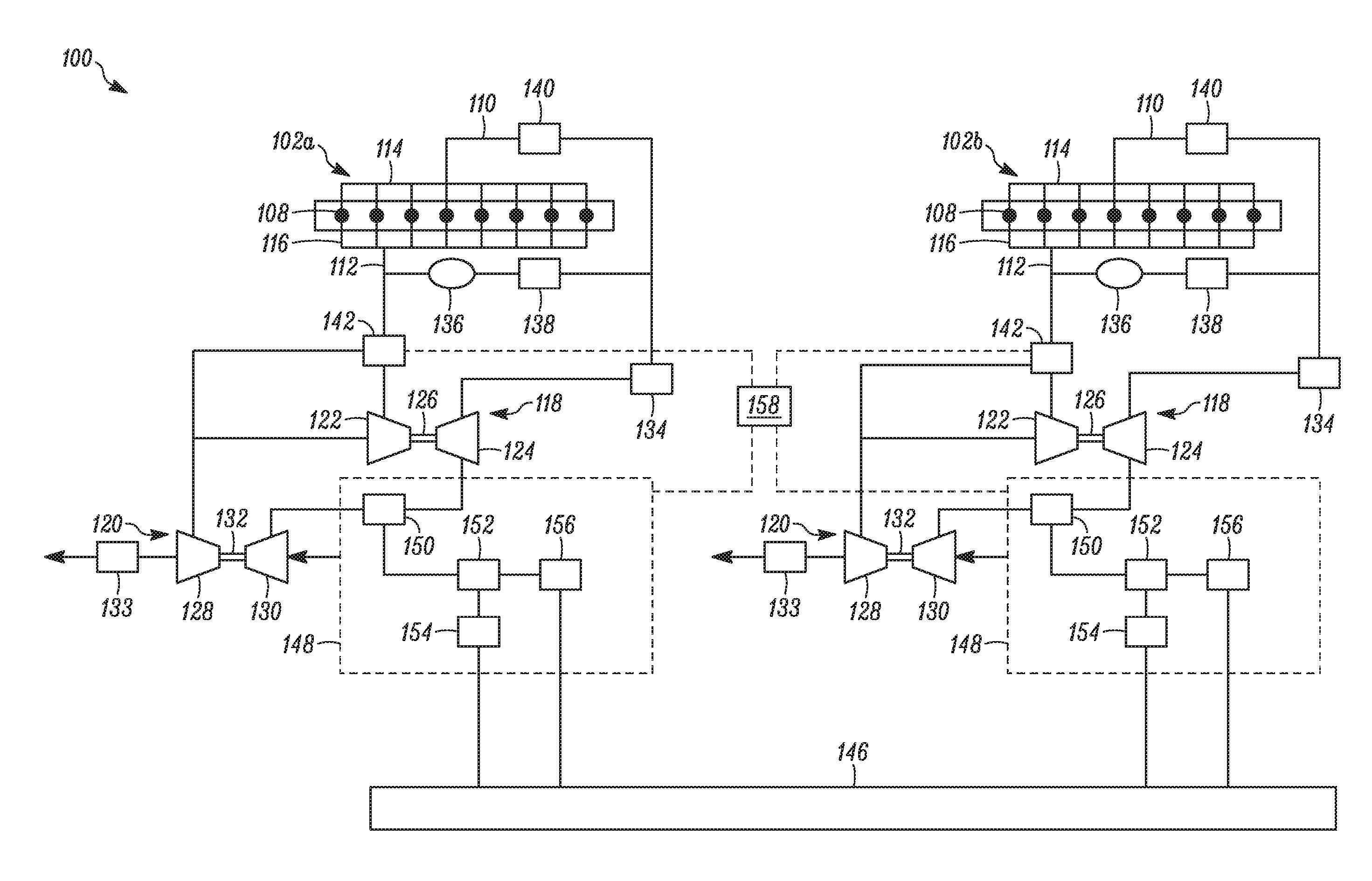
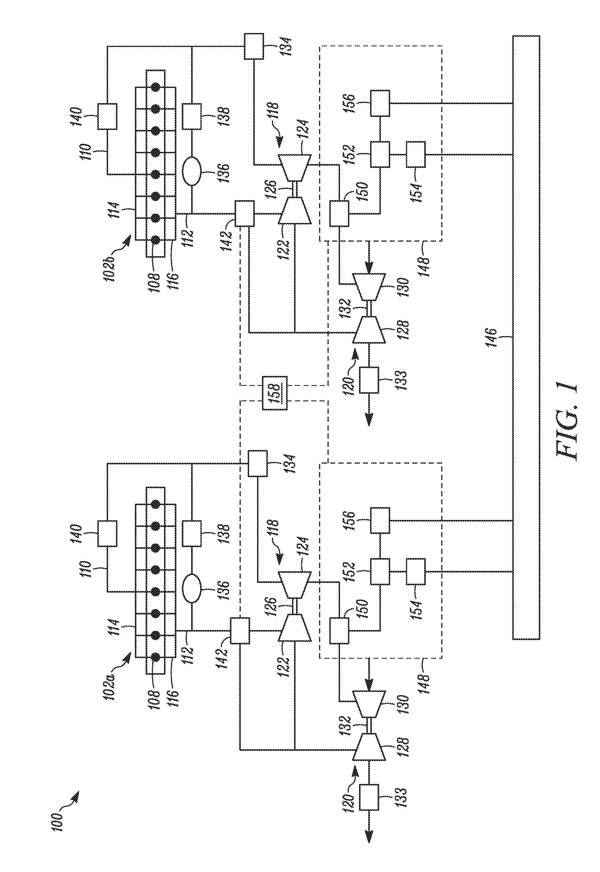
[0011]Wherever possible, the same reference numbers will be used throughout the drawings to refer to the same or the like parts. Referring to FIG. 1, a system 100 having multiple engines is illustrated. Although, two engines 102a, 102b (also collectively referred to as the engine / s 102) are shown, it may be recognized that the system 100 may include any number of engines. In the illustrated embodiment, the engines 102a and 102b are substantially similar to each other having similar type of components. However, in other embodiments, the engines 102a, 102b may be different from each other. For example, the engines 102a, 102b may have different configurations.

[0012]The engines 102 may be an internal combustion engine having a plurality of cylinders 108. In the example illustrated in FIG. 1, the cylinders 108 are arranged in an in-line configuration. However, the present disclosure is independent of the particular cylinder arrangement and may also be applied to V-type, rotary configurat...


PUM


Abstract

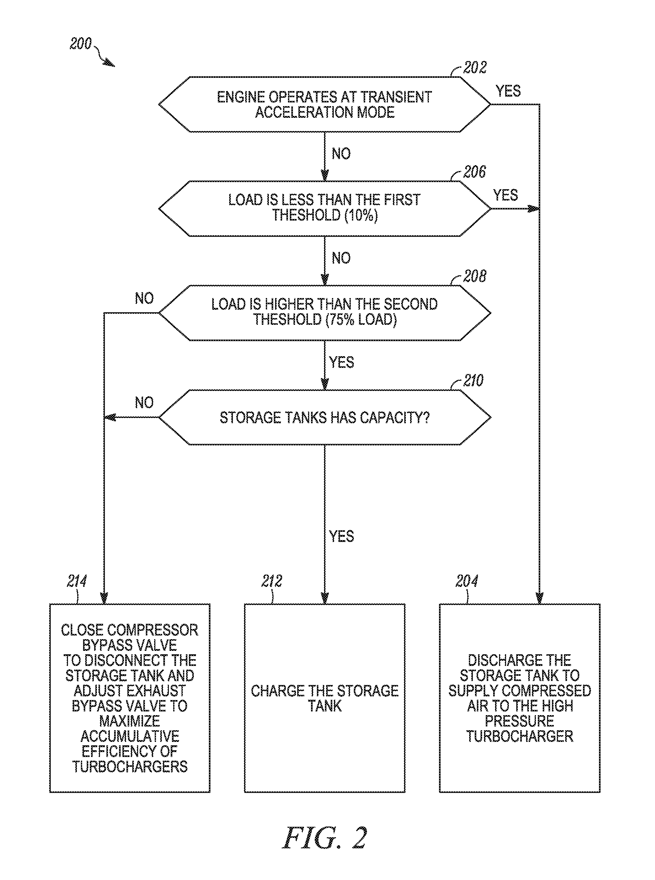
A system having an engine is provided. The system includes a high pressure (HP) turbocharger and a low pressure (LP) turbocharger connected in series with each other. The system also includes a first valve assembly configured to selectively bypass at least a portion of the exhaust from the engine to the LP turbocharger. The system also includes a storage tank configured to store a pressurized fluid and configured to be in fluid communication with the HP turbocharger and the LP turbocharger. The system further includes a second valve assembly in fluid communication with the storage tank, the HP turbocharger and the LP turbocharger. The system also includes a controller operatively coupled to the first valve assembly and the second valve assembly. The controller is configured to selectively operate the first valve assembly and the second valve assembly based on a change in a load requirement on the engine.

Description

TECHNICAL FIELD[0001]The present disclosure relates to a common rail system having multiple engines, and more particularly, to a system and a method of controlling fluid communication for turbochargers associated with each of the multiple engines.BACKGROUND[0002]Generally, in rig applications, such as drilling rigs and production platforms, an electric power is supplied by one or more generators. The rig applications may include pumps, motors, drive system(s), pipe racking systems, hydraulic power units, and / or a variety of rig utilities. The generators may run on natural gas or diesel fuel or other hydrocarbon fuel. In some cases, a response to external loads by an engine of these rig applications may be sluggish, when the engine runs on natural gas. Various turbochargers may be configured to utilize exhaust from the engine and supply a compressed air for operation of the engine. However, there may be a lag from turbochargers in responding to different power demands thereby effecti...

Claims


Application Information

Patent Timeline
IPC IPC(8): F02B37/18F02B37/013
CPCF02B37/013F02B37/18F02B21/00F02B33/44F02B37/004F02B73/00F02D25/00F02D41/0007F02D41/04F02D41/062Y02T10/12
Inventor GE, XINYUQI, YONGLI
Owner CATERPILLAR INC
Learn More