Exposure apparatus, exposure method, method of manufacturing device, program, and storage medium
a technology of exposure apparatus and manufacturing method, which is applied in the direction of microlithography exposure apparatus, photomechanical treatment, instruments, etc., can solve the problems of exposure defect probability and defective device possibility, and achieve the effect of suppressing the occurrence of exposure defect and suppressing the occurrence of defective devi
- Summary
- Abstract
- Description
- Claims
- Application Information
AI Technical Summary
Benefits of technology
Problems solved by technology
Method used
Image
Examples
first embodiment
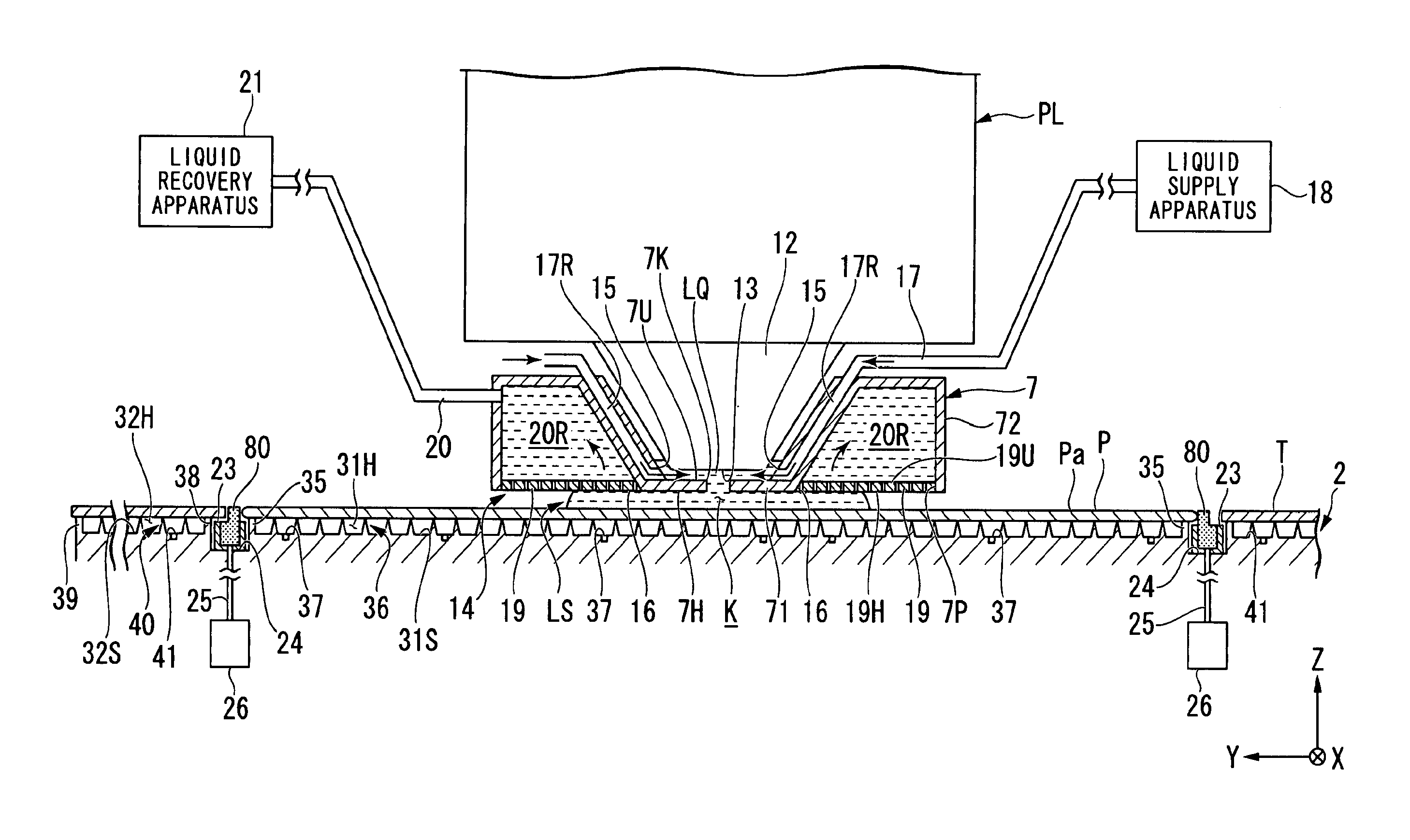
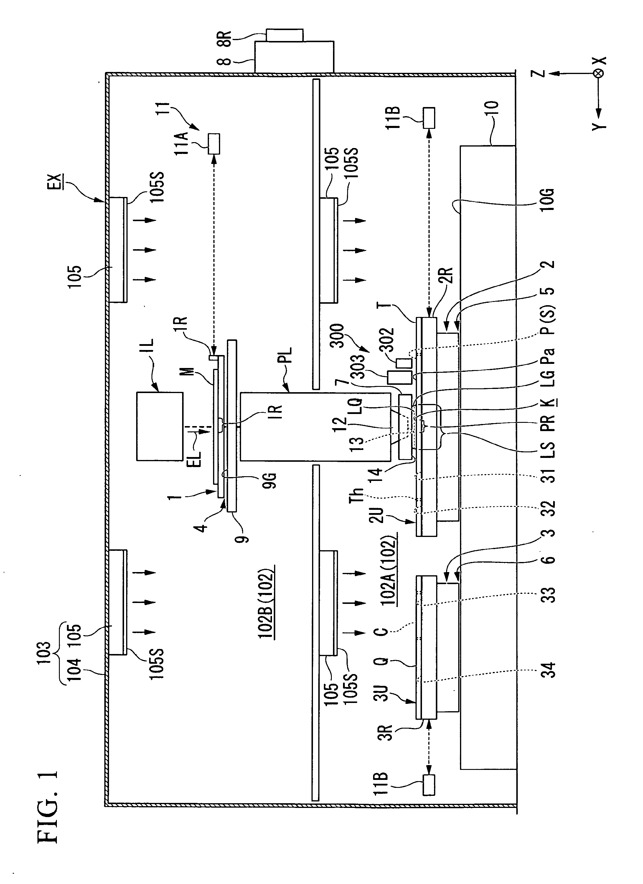
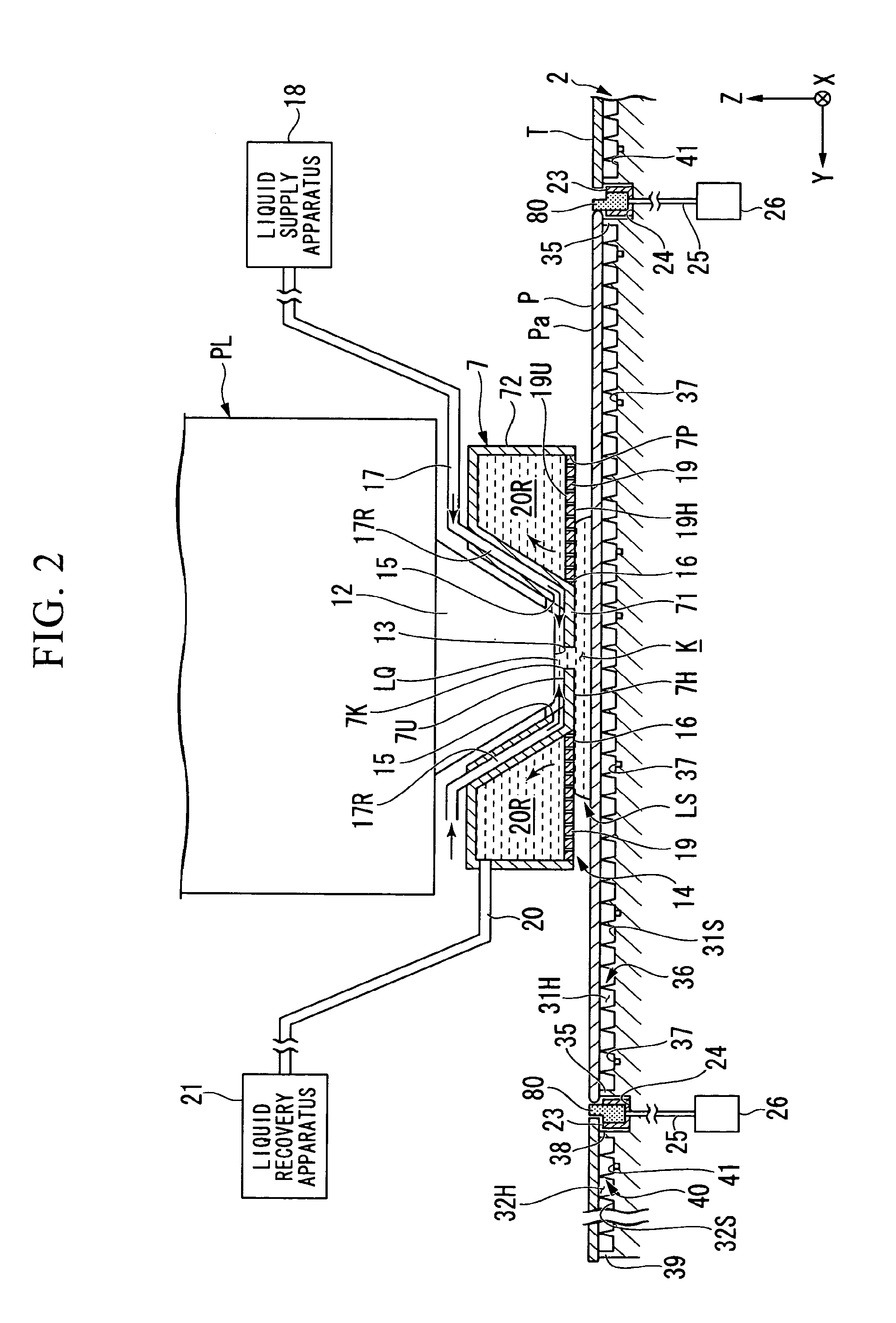
[0103]A first embodiment is described. FIG. 1 is a schematic configuration view illustrating one example of an exposure apparatus EX relating to the first embodiment. The exposure apparatus EX of the present embodiment is a liquid immersion exposure apparatus exposing a substrate P with exposure light EL through liquid LQ. In the present embodiment, a liquid immersion space LS is formed in such a manner that at least a part of the light path of the exposure light EL is filled with the liquid LQ. The liquid immersion space is a part (a space, or an area) which is filled with liquid. The substrate P is exposed by the exposure light EL through the liquid LQ in the liquid immersion space LS. In the present embodiment, water (purified water) is used as the liquid LQ.
[0104]Furthermore, the exposure apparatus EX of the present embodiment is an exposure apparatus equipped with a substrate stage and a measurement stage, for example, as disclosed in the specification of U.S. Pat. No. 6,897,96...
second embodiment
[0234]Next, a second embodiment is described. In the below-written description, the same component as or the equivalent component to the component of the above-described embodiment is given a like reference numeral and therefore its description is brief or omitted.
[0235]FIG. 8 is a view illustrating one example of a substrate stage 200A relating to the second embodiment. As shown in FIG. 8, in the present embodiment, a porous member 80 is arranged in such a manner that a second side surface 80C of a porous member 80 and an inside surface Tc of a cover member T come into contact with each other. Furthermore, in an example shown in FIG. 8, a support member 82 is omitted. Furthermore, in the example shown in FIG. 8, a support member 82 may be also arranged.
[0236]Furthermore, in the present embodiment, a substrate stage 200A includes the temperature adjustment apparatus 305 adjusting the temperature of the porous member 80. The temperature adjustment apparatus 305 includes, for example,...
third embodiment
[0244]Next, a third embodiment is described. In the below-written description, the same component as or the equivalent component to the component of the above-described embodiment is given a like reference numeral and therefore its description is brief or omitted.
[0245]FIG. 9 is a view illustrating one example of a substrate stage 200B relating to the third embodiment. In FIG. 9, a porous member 800B includes a part 801B in the form of a plate, a part 802B in the form of a plate, and a part 803B in the form of a rod.
[0246]The part 801B is arranged at a space portion 23 in such a manner as to face a gap Ga. The part 802B is arranged at a space portion 23 in such a manner as to face the suction port 24. The part 803B is arranged between the part 801B and the part 802B.
[0247]In the present embodiment, the porous member 800B is not provided in the gap Ga. Furthermore, at least a part of the porous member 800B (the part 801B) may be arranged at the gap Ga.
[0248]Furthermore, in an example...
PUM
| Property | Measurement | Unit |
|---|---|---|
| wavelength | aaaaa | aaaaa |
| wavelength | aaaaa | aaaaa |
| wavelength | aaaaa | aaaaa |
Abstract
Description
Claims
Application Information
 - R&D
- Intellectual Property
- Life Sciences
- Materials
- Tech Scout
- Unparalleled Data Quality
- Higher Quality Content
- 60% Fewer Hallucinations
Browse by: Latest US Patents, China's latest patents, Technical Efficacy Thesaurus, Application Domain, Technology Topic, Popular Technical Reports.
© 2025 PatSnap. All rights reserved.Legal|Privacy policy|Modern Slavery Act Transparency Statement|Sitemap|About US| Contact US: help@patsnap.com


