Method of manufacturing plastic lens, method of positioning film, and composite body
a technology of positioning film and plastic lens, which is applied in the direction of polarising elements, instruments, spectales/goggles, etc., can solve the problems of many defects of polarizing film being exposed from the eyepiece surface, and affect the aesthetics of the eyepiece, so as to reduce the manufacturing cost and suppress the occurrence of defective products , the effect of easy distance checking
- Summary
- Abstract
- Description
- Claims
- Application Information
AI Technical Summary
Benefits of technology
Problems solved by technology
Method used
Image
Examples
first embodiment
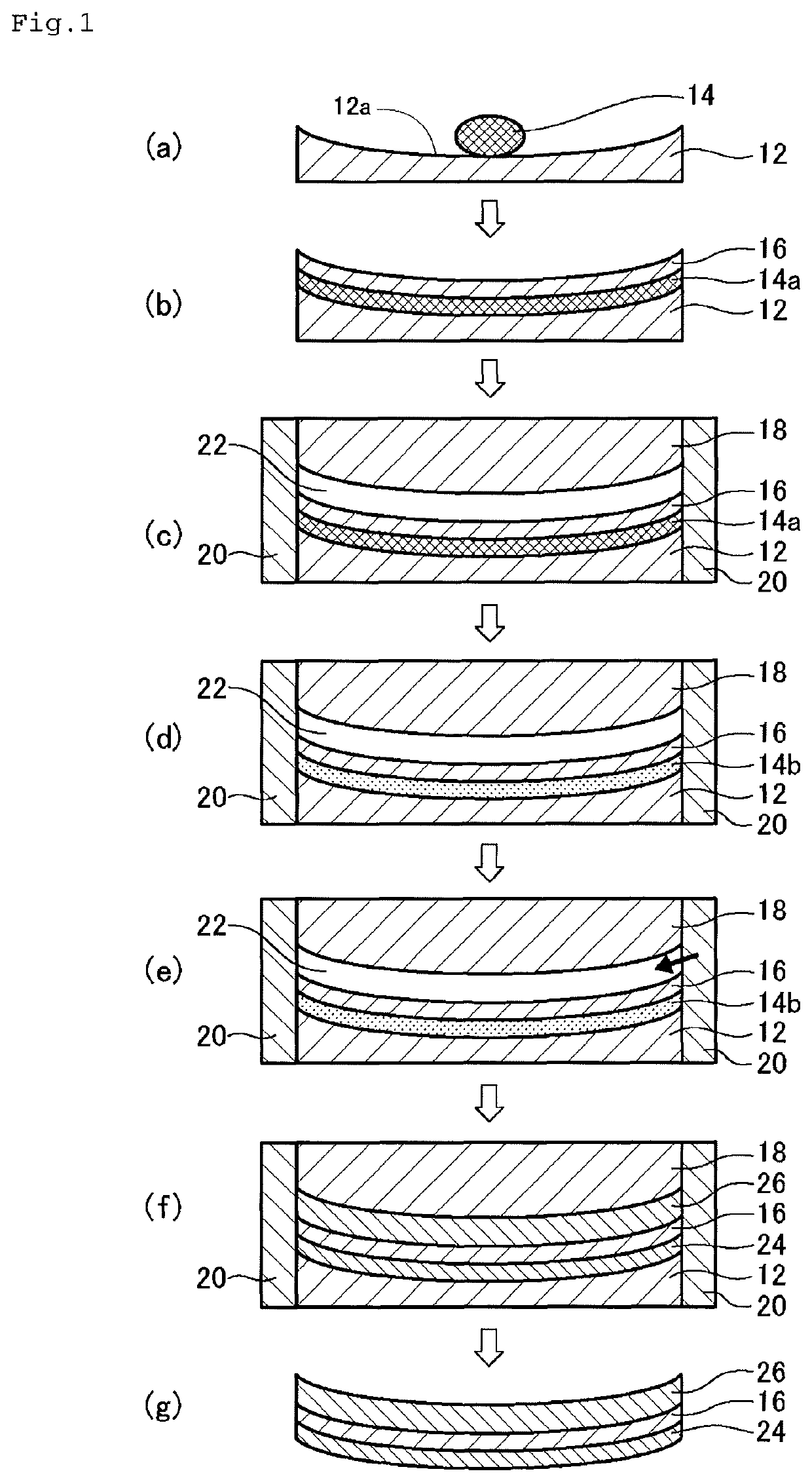
[0082]The method of manufacturing a plastic lens according to this embodiment includes the following steps.
[0083]Step a: a predetermined amount of a first curable composition 14 is put over a forming surface 12a of a first mold substrate 12 having the forming surface 12a for forming an objective surface of a lens (FIG. 1(a)).
[0084]Step b: the first curable composition 14 is spread over the entire forming surface 12a by pressing the composition 14 with a film 16 to form a first curable composition layer 14a, and the first mold substrate 12 and the film 16 are separated from each other by a predetermined distance through the first curable composition layer 14a (FIG. 1(b)).
[0085]Step c: an outer edge of the first mold substrate 12, an outer edge of the film 16, and an outer edge of a second mold substrate 18 having a forming surface for forming the other surface of the lens are covered with a fastening member 20 to support them in place, and the second mold substrate 18 is placed so as...
second embodiment
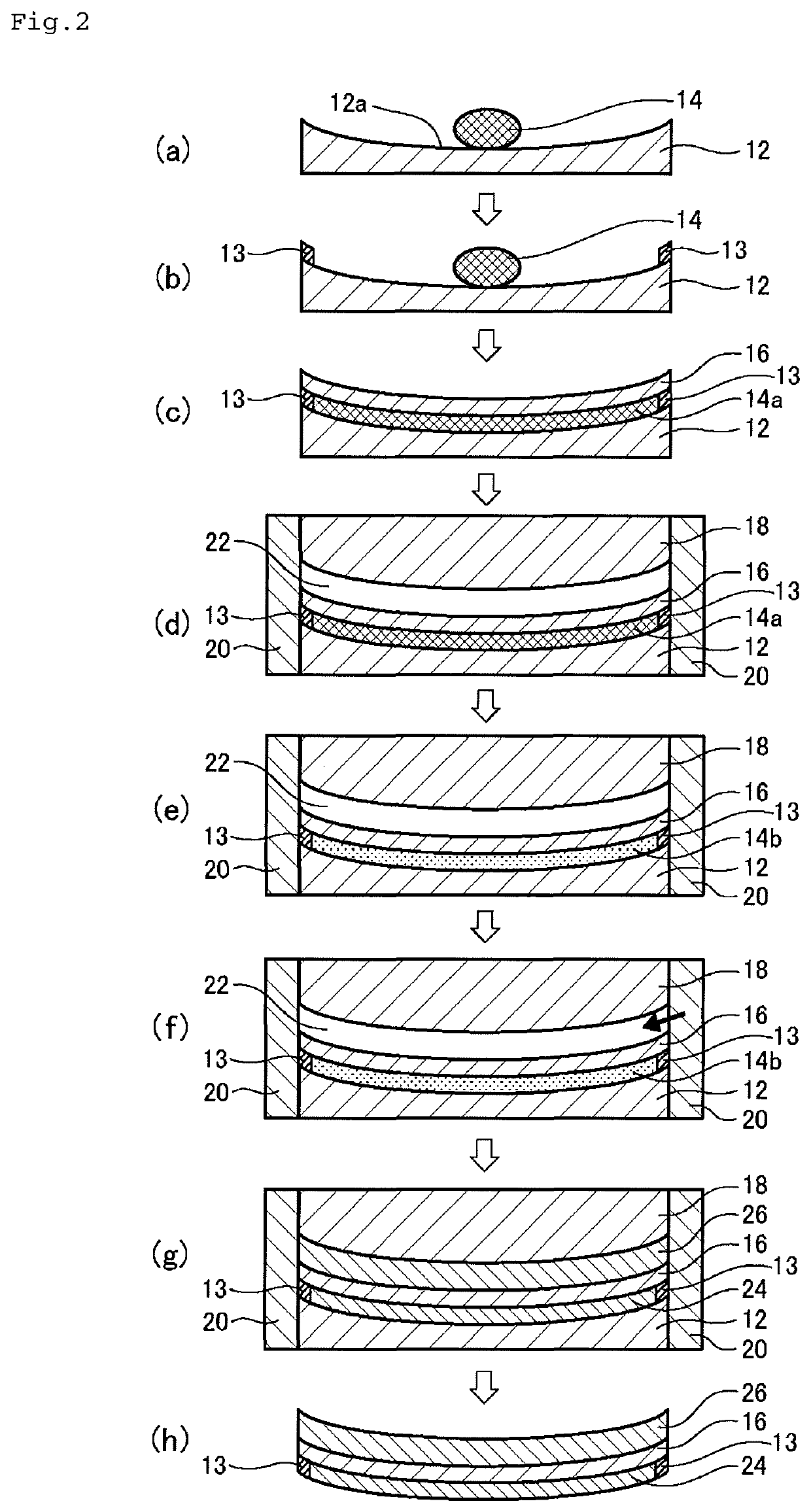
[0159]The method of manufacturing a plastic lens according to this embodiment includes the following steps.
[0160]Step a: a predetermined amount of a first curable composition 14 is put over a forming surface 12a of a first mold substrate 12 having the forming surface 12a for forming an objective surface of a lens (FIG. 2(a)).
[0161]Step b: a spacer 13 is placed over a forming surface 12a of a first mold substrate 12 having the forming surface 12a for forming an objective surface of a lens (FIG. 2(b)).
[0162]Step c: the first curable composition 14 is spread over the entire forming surface 12a by pressing the composition 14 with a film 16 to form a first curable composition layer 14a, and the first mold substrate 12 and the film 16 are separated from each other by a predetermined distance through the first curable composition layer 14a (FIG. 2(c)).
[0163]Step d: an outer edge of the first mold substrate 12, an outer edge of the spacer 13, an outer edge of the film 16, and an outer edge ...
third embodiment
[0177]The method of manufacturing a plastic lens according to this embodiment includes the following steps.
[0178]Step a: a first curable composition having a viscosity of 1,000 mPa·s to 100,000 mPa·s is put over a forming surface of a first mold substrate having the forming surface for forming an objective surface of a lens.
[0179]Step b: the first curable composition is spread over the entire forming surface by pressing the composition with a film to form a first curable composition layer, and the first mold substrate and the film are separated from each other by a predetermined distance through the first curable composition layer.
[0180]Step c: an outer edge of the first mold substrate, an outer edge of the film, and an outer edge of a second mold substrate having a forming surface for forming the other surface of the lens are covered with a fastening member to support them in place, and the second mold substrate is placed so as to be opposed to the film with being spaced apart from...
PUM
| Property | Measurement | Unit |
|---|---|---|
| storage elastic modulus | aaaaa | aaaaa |
| storage elastic modulus | aaaaa | aaaaa |
| viscosity | aaaaa | aaaaa |
Abstract
Description
Claims
Application Information
 - R&D
- Intellectual Property
- Life Sciences
- Materials
- Tech Scout
- Unparalleled Data Quality
- Higher Quality Content
- 60% Fewer Hallucinations
Browse by: Latest US Patents, China's latest patents, Technical Efficacy Thesaurus, Application Domain, Technology Topic, Popular Technical Reports.
© 2025 PatSnap. All rights reserved.Legal|Privacy policy|Modern Slavery Act Transparency Statement|Sitemap|About US| Contact US: help@patsnap.com


