Childproof discharging device

a discharging device and childproof technology, applied in the field of discharging devices, can solve the problems of frequent handling of discharging devices or dispensers with child locks, affecting the safety of children, so as to reduce the volume of the pump chamber, facilitate handling, and facilitate the effect of discharging

Active Publication Date: 2016-08-25
APTAR RADOLFZELL
View PDF23 Cites 19 Cited by
  • Summary
  • Abstract
  • Description
  • Claims
  • Application Information

AI Technical Summary

Benefits of technology

[0005]It is the object of the invention to develop generic discharging devices and dispensers further to the effect that with low structural expenditure an effective child lock and simple handling are achieved.

Problems solved by technology

The liquids to be discharged by way of generic discharging devices and dispensers also include liquids the ingestion of which can be harmful if they are not medically induced.
It is particularly problematic when children, for example out of curiosity or when playing, use pharmaceutical dispensers and in this case discharge and ingest liquid.
Depending on the liquid, this can be linked to considerable risks to the health of a child.
In many countries of the world the given problem has resulted in legislative measures, according to which in the case of certain pharmaceutical liquids or active substances only dispensers which cannot normally be opened or actuated by children are allowed to be used as children do not comprehend the mode of implementation.
The handling of corresponding dispensers or discharging devices with a child lock is frequently arduous.
This then once again results in the risk that unobstructed access to the media stored in the manipulated dispensers is possible for children.
Studies have shown that a combination of force or movement of this type is difficult for children, but intuitively possible for adults.
In this case, it has been shown that children, as a rule, are also not able to interpret symbolic representations of necessary operating steps for removing the protective cap.

Method used


Image

  • Childproof discharging device
  • Childproof discharging device
  • Childproof discharging device

Examples


Embodiment Construction

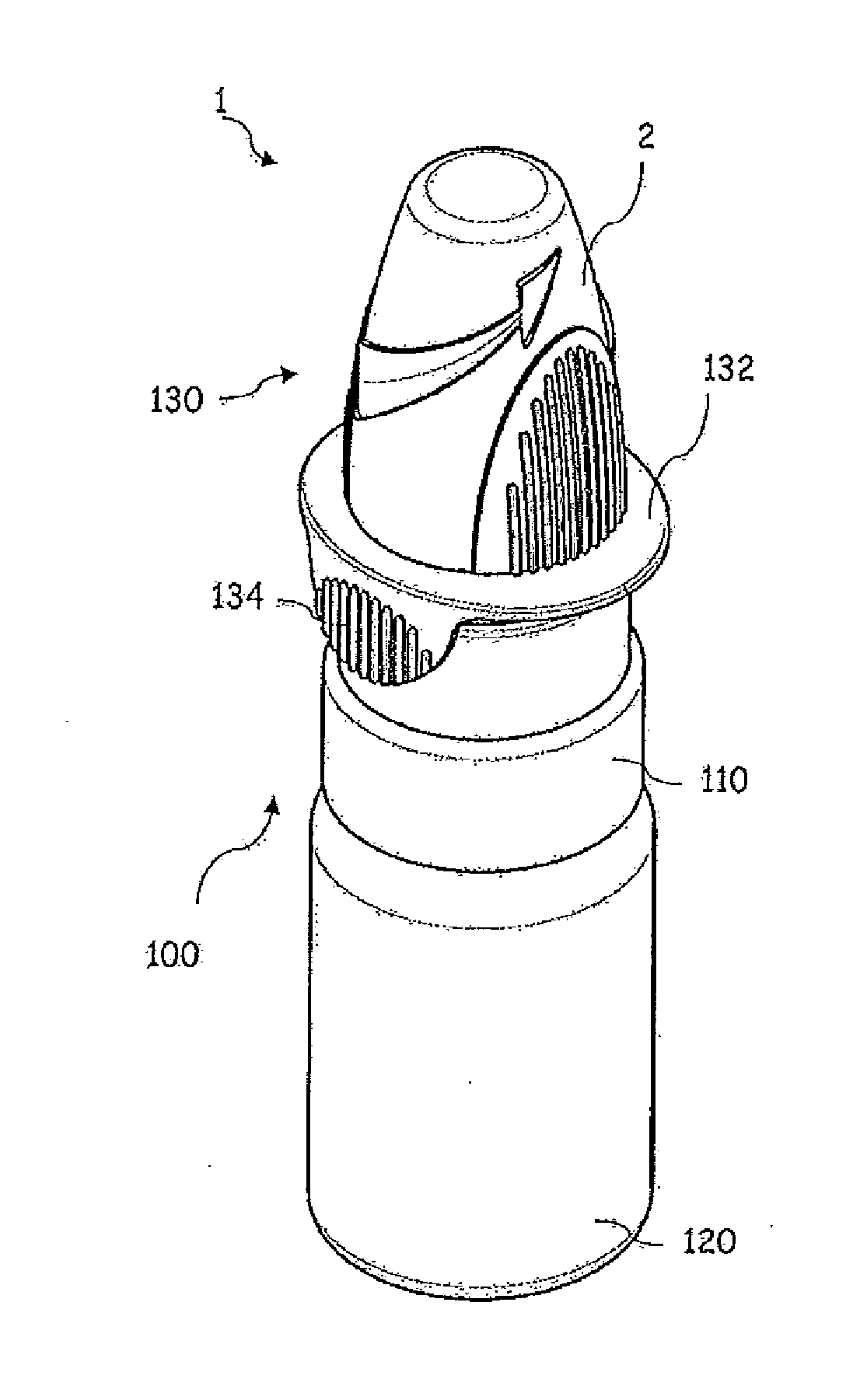
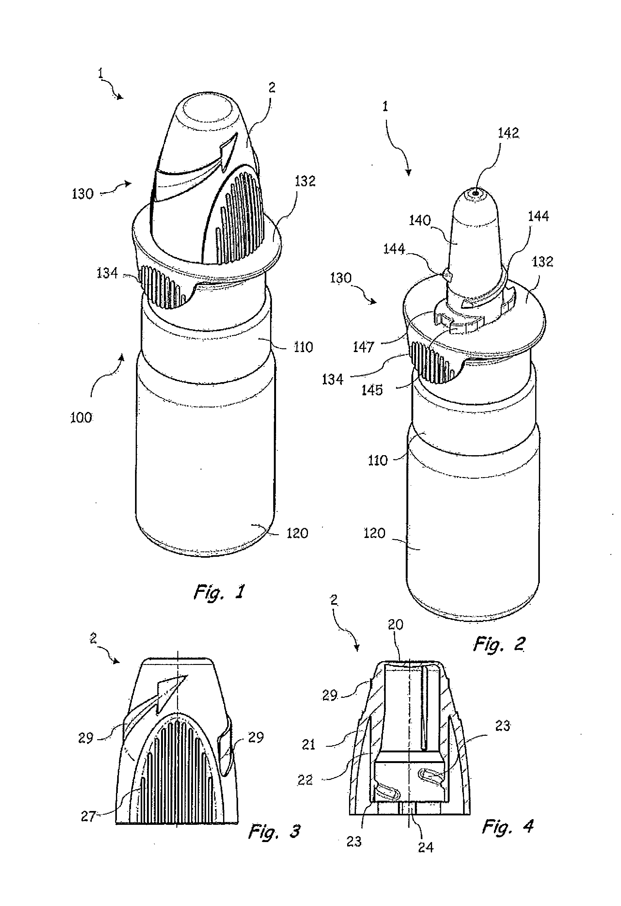
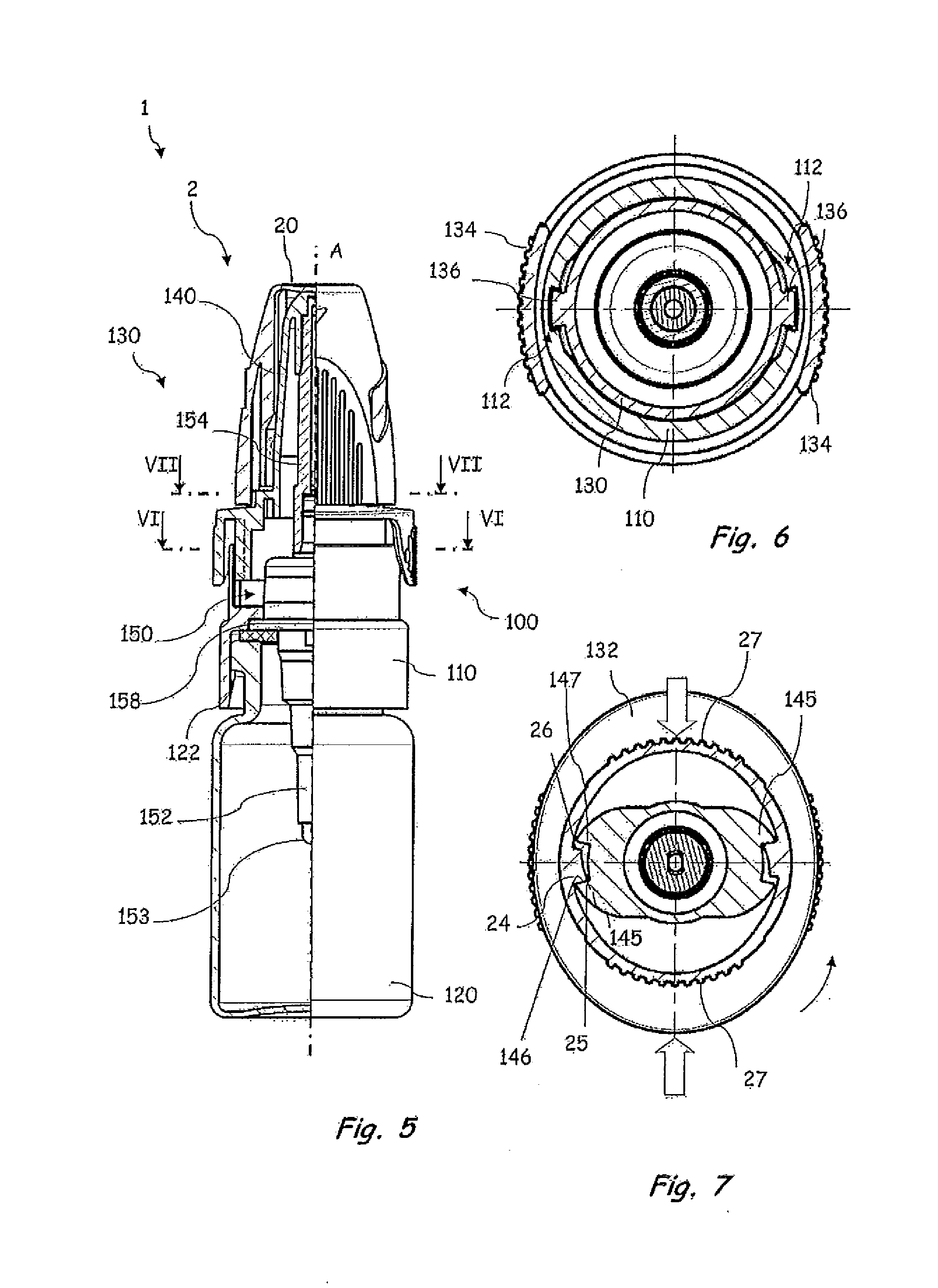
[0038]FIGS. 1 to 7 show a dispenser 1 with a discharging device 100 according to a first development of the invention. In this case, FIGS. 1 and 2 show perspective representations of the dispenser 1 with a protective cap 2 fitted in position or without a protective cap. FIGS. 3 and 4 show a side view and a sectioned representation of the protective cap 2. FIG. 5 shows a half-section view of the dispenser 100 and FIGS. 6 and 7 show sectioned top views of the dispenser 100 along cutting planes VI-VI or VII-VII according to FIG. 5.

[0039]The discharging device 100 shown in FIGS. 1, 2 and 5 to 7 has a housing 110 to which an external liquid storage unit 120 is coupled by means of a snap-type connection 122. On the side of the housing 110 remote from the liquid storage unit 120, the discharging device 100 shown comprises an actuation unit 130 which has a finger support surface 132. An applicator tip 140, which is developed as a nose olive and on the distal end of which a discharge opening...


PUM


Abstract

A discharging device for a pharmaceutical liquid dispenser including a housing, an applicator tip with a discharge opening and a protective cap. A locking tooth is provided on the protective cap and a counter tooth is provided on the applicator tip. The locking tooth passes over the counter tooth when the protective cap is rotated relative to the applicator tip in a first direction, and the locking tooth and the counter tooth prevent rotation in a direction opposite the first direction. The protective cap and the applicator tip are adapted to each other such that the discharge opening contacts a lid region of the protective cap after the locking tooth has passed over the counter tooth, and the discharge opening can be closed in a sealed manner by the protective cap. The protective cap is deformable to disengage the locking tooth and the counter tooth.

Description

SCOPE AND PRIOR ART[0001]The invention relates to a discharging device for a dispenser for discharging pharmaceutical liquids, said discharging device including a housing having a coupling geometry for mounting on a liquid storage unit, an applicator tip having a discharge opening arranged on a distal end and a protective cap. The invention further relates to a dispenser for discharging pharmaceutical liquids, said dispenser including a liquid storage unit and a discharging device.[0002]The liquids to be discharged by way of generic discharging devices and dispensers also include liquids the ingestion of which can be harmful if they are not medically induced. It is particularly problematic when children, for example out of curiosity or when playing, use pharmaceutical dispensers and in this case discharge and ingest liquid. Depending on the liquid, this can be linked to considerable risks to the health of a child.[0003]In many countries of the world the given problem has resulted in...

Claims


Application Information

Patent Timeline
Patent Type & Authority Applications(United States)
IPC IPC(8): A61M11/00B05B11/00
CPCB05B11/0032B65D50/046A61M2205/276B05B11/3047A61M15/08A61M11/007A61M15/009A61M15/00B65D50/04B05B11/1047
Inventor SZYMICZEK, CHRISTOPHKRAMPEN, GERALDGREINER-PERTH, JUERGEN
Owner APTAR RADOLFZELL
Why Eureka
Try Eureka