Light grid
a light grid and grid technology, applied in the field of light grids, can solve the problems of detection errors, signal jumps in the receiving signal, and distortion of the receiving signal, and achieve the effect of low structural expenditur
- Summary
- Abstract
- Description
- Claims
- Application Information
AI Technical Summary
Benefits of technology
Problems solved by technology
Method used
Image
Examples
first embodiment
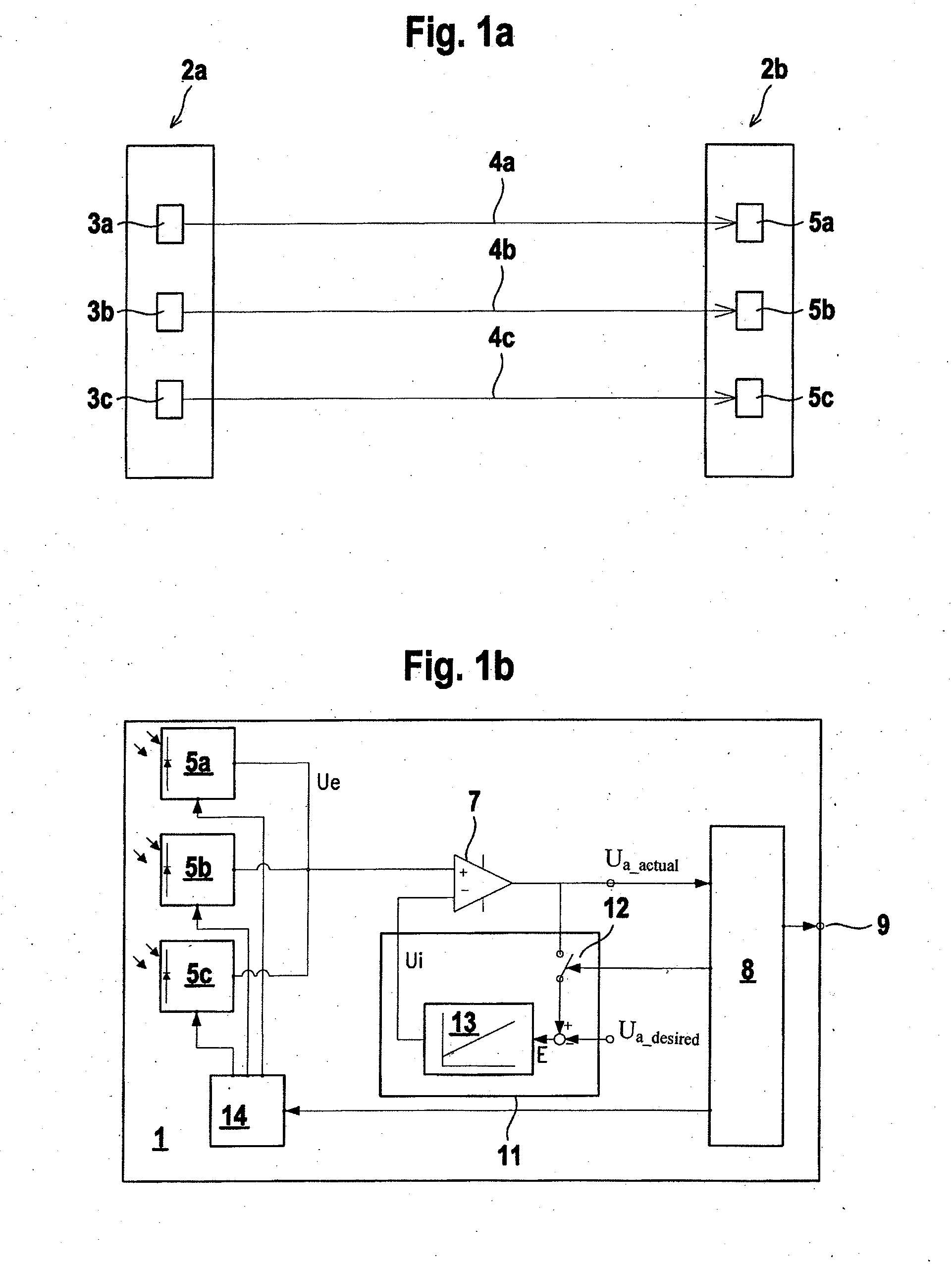
[0037]FIG. 3 shows a subtracting element which is integrated into the amplifier 7 of the arrangement according to FIG. 1b and / or which forms this amplifier. An analog integrator 13 is used for the control operation, for which the time constant can be adjusted with the aid of the resistance R and the capacitor C. Since the voltage Udesired forms the reference for the integrator 13, this voltage also adjusts for Ua.
second embodiment
[0038]FIG. 4 shows the control unit 11, wherein the output signal Ua is compared with the aid of a comparator 15 to a desired value for the operating point and a switch mechanism 16 (e.g. in the form of an up / down counter) readjusts a DA converter 17 in such a way that the output signal Ua approaches the desired operating value gradually but expeditiously.
[0039]The switch mechanism 16 assumes the function of the switch 12 in FIG. 1b, wherein the switch mechanism 16 comprises a control input. Depending on the control signal present at the control input, the switch mechanism 16 assumes two different states. In a compensating state, input information is accordingly transmitted by the switch mechanism 16 to its output and is emitted there. In a freeze state, this transfer of information is blocked.
third embodiment
[0040]FIG. 5 shows the control unit 11, wherein a request is posed via an AD converter 18 for the output signal Ua. The digital embodiment of the control unit 11 has the advantage that no drift or offset errors occur and that the switch 12 for freezing the operating point can be omitted. Here too, the switch mechanism 16 takes over the function of the switch 12, in the same way as for the embodiment according to FIG. 4. For the embodiment according to FIG. 5, the function of the compensator 15, illustrated in FIG. 4, is integrated into the AD converter.
PUM
 Abstract
Description
Claims
Application Information
 - R&D
- Intellectual Property
- Life Sciences
- Materials
- Tech Scout
- Unparalleled Data Quality
- Higher Quality Content
- 60% Fewer Hallucinations
Browse by: Latest US Patents, China's latest patents, Technical Efficacy Thesaurus, Application Domain, Technology Topic, Popular Technical Reports.
© 2025 PatSnap. All rights reserved.Legal|Privacy policy|Modern Slavery Act Transparency Statement|Sitemap|About US| Contact US: help@patsnap.com


