Image forming system, image forming apparatus and information processing apparatus

a technology of image forming and information processing, applied in the field of image forming system, image forming apparatus and information processing apparatus, can solve the problem that users cannot obtain the desired

Active Publication Date: 2016-08-25
OKI ELECTRIC IND CO LTD
View PDF13 Cites 6 Cited by
  • Summary
  • Abstract
  • Description
  • Claims
  • Application Information

AI Technical Summary

Benefits of technology

[0013]According to this invention, when image blocks are formed on a s...

Problems solved by technology

Therefore, when image blocks are formed on a sheet, the user can...

Method used


Image

  • Image forming system, image forming apparatus and information processing apparatus
  • Image forming system, image forming apparatus and information processing apparatus
  • Image forming system, image forming apparatus and information processing apparatus

Examples


first embodiment

1. First Embodiment

1-1. Structure

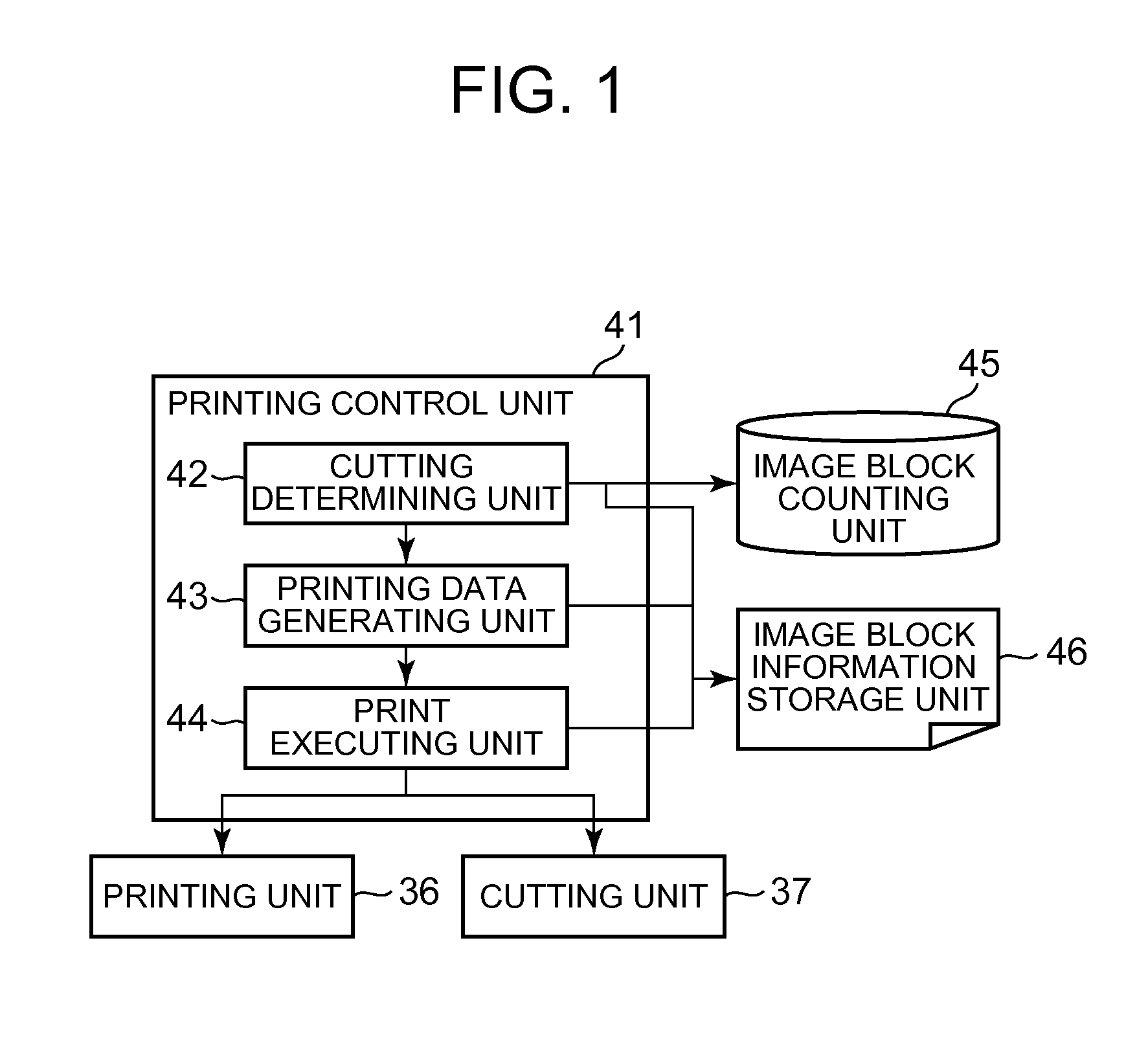
[0031]FIG. 2 is a block diagram showing the configuration of an image forming system 1.

[0032]As shown in FIG. 2, the image forming system 1 may include an image processing apparatus 10 and a printing apparatus 30. The image processing apparatus 10 and the printing apparatus 30 are connected to one another through a network 50 as a transmission medium. The image processing apparatus 10 performs image processing on block data. The image processing apparatus 10 outputs a printing job including image data corresponding to image blocks to the printing apparatus 30. The printing apparatus 30 forms image blocks on a continuous printing sheet based on the inputted printing job.

[0033]The image processing apparatus 10 may a Personal Computer (PC), a workstation or other information processing apparatus. The image processing apparatus 10 executes image processing for the block data, print setting processing, and so on. The image processing apparatus 10 outputs ...

second embodiment

2. Second Embodiment

2-1. Structure

[0077]FIG. 14 is a block diagram showing the configuration of an image forming system 90.

[0078]In the second embodiment, the structure of a printer driver 71 included the image processing apparatus 100 and the structure of a printing control unit 81 included the printing apparatus 300 are different from the printer driver 21 and the printing control unit 41 in the first embodiment.

[0079]FIG. 14 is a block diagram showing the configuration of an image forming system 90.

[0080]As shown in FIG. 14, the image forming system 90 may include an image processing apparatus 100 and a printing apparatus 300. The internal memory apparatus 15 stores a printer driver program 70. The ROM 35 stores a printing control unit program 80. Other structure is same as the structure in the first embodiment. Therefore the explanation is omitted.

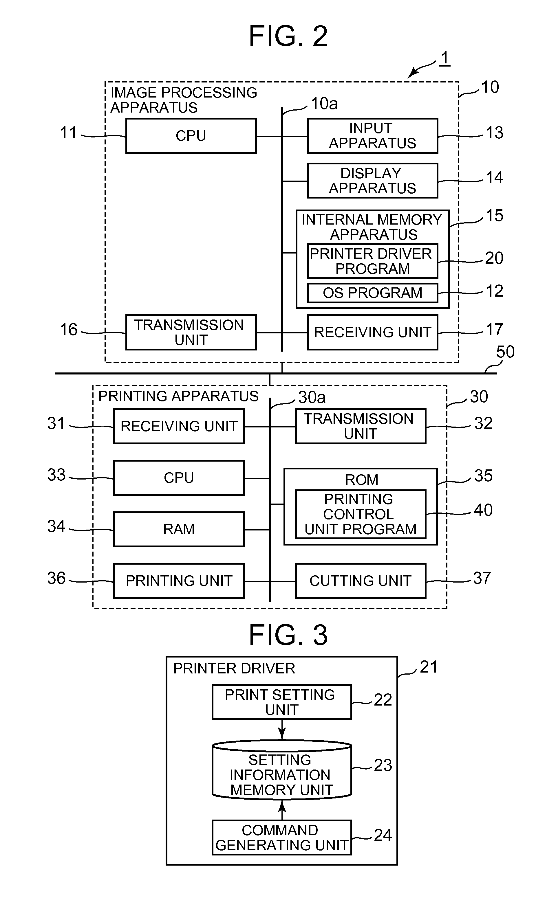
[0081]FIG. 9 is a block diagram showing the configuration of the printer driver 71. FIG. 10 is a schematic view showing a print setti...


PUM


Abstract

An image forming system for printing a sequence of image blocks on a continuous printing sheet based on image data, includes an information processing apparatus and an image forming apparatus. A printing setting unit included by the information processing apparatus designates first information and second information. The first information indicates whether a printing order of the image blocks is to be a normal order or a reverse order. The second information indicates how many image blocks of the sequence are to be printed on each of a plurality of segments of the printing sheet. The image forming apparatus includes a cutting unit and a control unit. The cutting unit cuts the printing sheet. The control unit controls the cutting unit so as to separate the segments of the printing sheet. The control unit determines cutting positions on the printing sheet based on the first information and the second information.

Description

CROSS REFERENCE TO RELATED APPLICATIONS[0001]This application claims priority based on 35 USC 119 from prior Japanese Patent Application No. 2015-030609 filed on Feb. 19, 2015, the entire contents which are incorporated herein by reference.BACKGROUND OF THE INVENTION[0002]1. Field of the Invention[0003]This application is directed to an image forming system, an image forming apparatus, and an information processing apparatus.[0004]2. Description of Related Art[0005]A conventional image forming apparatus forms image blocks on a sheet based on image data. The conventional image forming apparatus cuts the sheet every designated block number (see, for example, Japanese Laid-open Patent Publication No. 2010-97008, and corresponding published application US2010 / 0098445).[0006]A strip printer (continuous medium printer) is a type of an image forming apparatus that forms image blocks on an elongated continuous printing sheet that is subsequently cut into segments. The sheet is typically pap...

Claims


Application Information

Patent Timeline
IPC IPC(8): G06K15/02G06K15/00
CPCG06K15/022G06K15/1807G06K15/404G06F3/1205G06F3/1251G06F3/1253G06F3/1286G06K15/1806H04N1/00676B41J3/4075B41J11/663G03G15/6523
Inventor SHIRASAKA, MITSUYOSHI
Owner OKI ELECTRIC IND CO LTD
Why Eureka
Try Eureka