
Transformer for reducing eddy current losses of coil

a transformer and eddy current technology, applied in transformers/inductances magnetic cores, basic electric elements, electrical equipment, etc., can solve the problems of affecting the long-time the conductor has a drawback which is difficult to apply for maintaining mechanical strength, and the local overheating affects the long-term operation reliability of the transformer. achieve the effect of reducing eddy current losses

Active Publication Date: 2016-08-25
LSIS CO LTD
View PDF1 Cites 0 Cited by
  • Summary
  • Abstract
  • Description
  • Claims
  • Application Information

AI Technical Summary

Benefits of technology

The patent is about a transformer that reduces eddy current losses caused by leakage flux. It does this by using a cut part on the ends of the coils that surround the core of the transformer. This cut part removes a portion of the conductor to reduce the influence of leakage flux. By doing this, the transformer is more stable and durable, and it does not compromise its insulating strength. This reduces heat and improves the performance of the device that uses the transformer.

Problems solved by technology

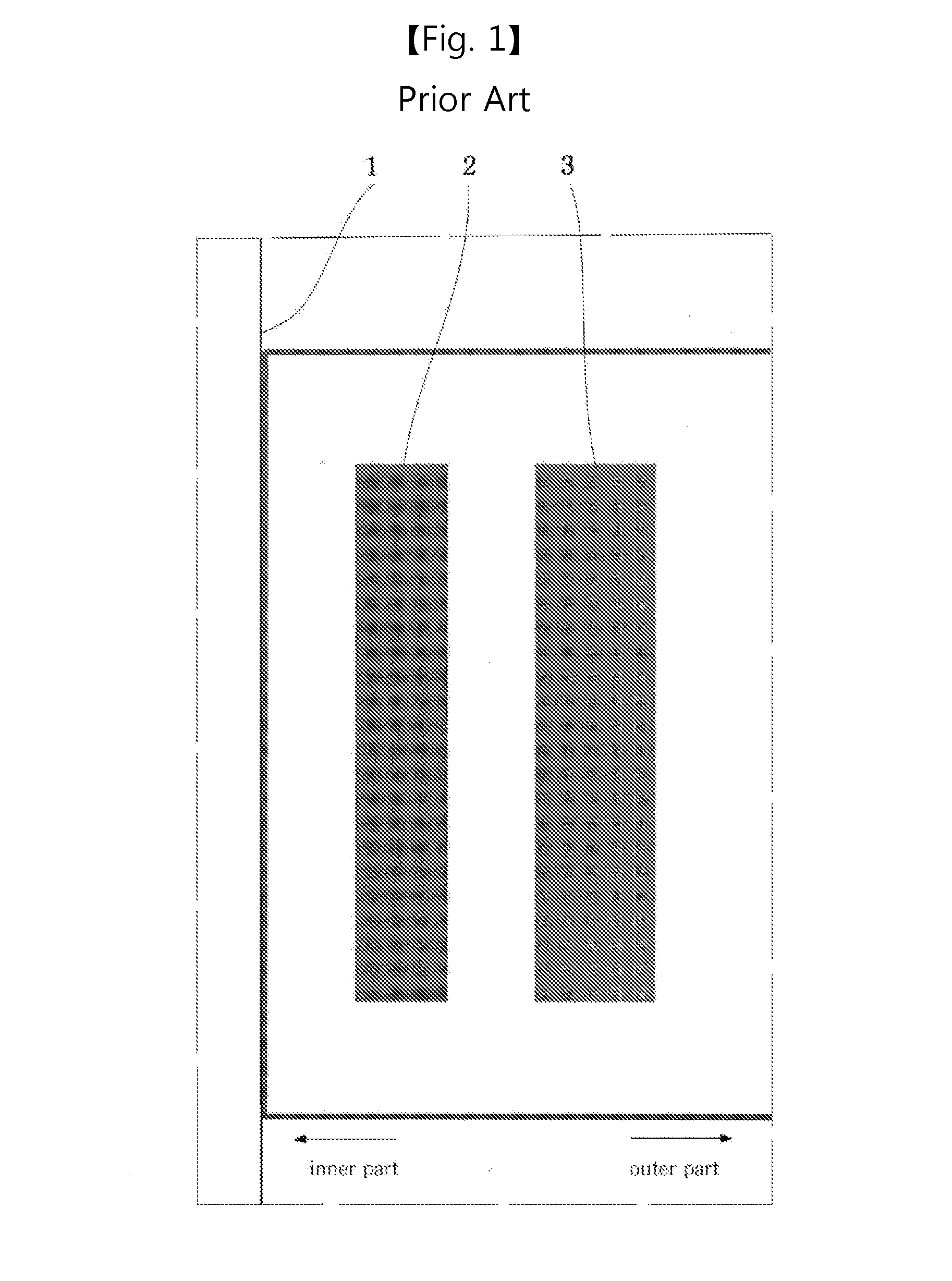
In the load loss, most of losses are direct current (DC) resistance losses caused by a coil resistance, but stray load loss and eddy current loss which occurs in a coil, a supporting structure, and a tank due to leakage flux cannot be neglected.
In particular, eddy current loss which occurs in a coil causes local overheating, and is a factor that largely affects long-time operation reliability of a transformer.
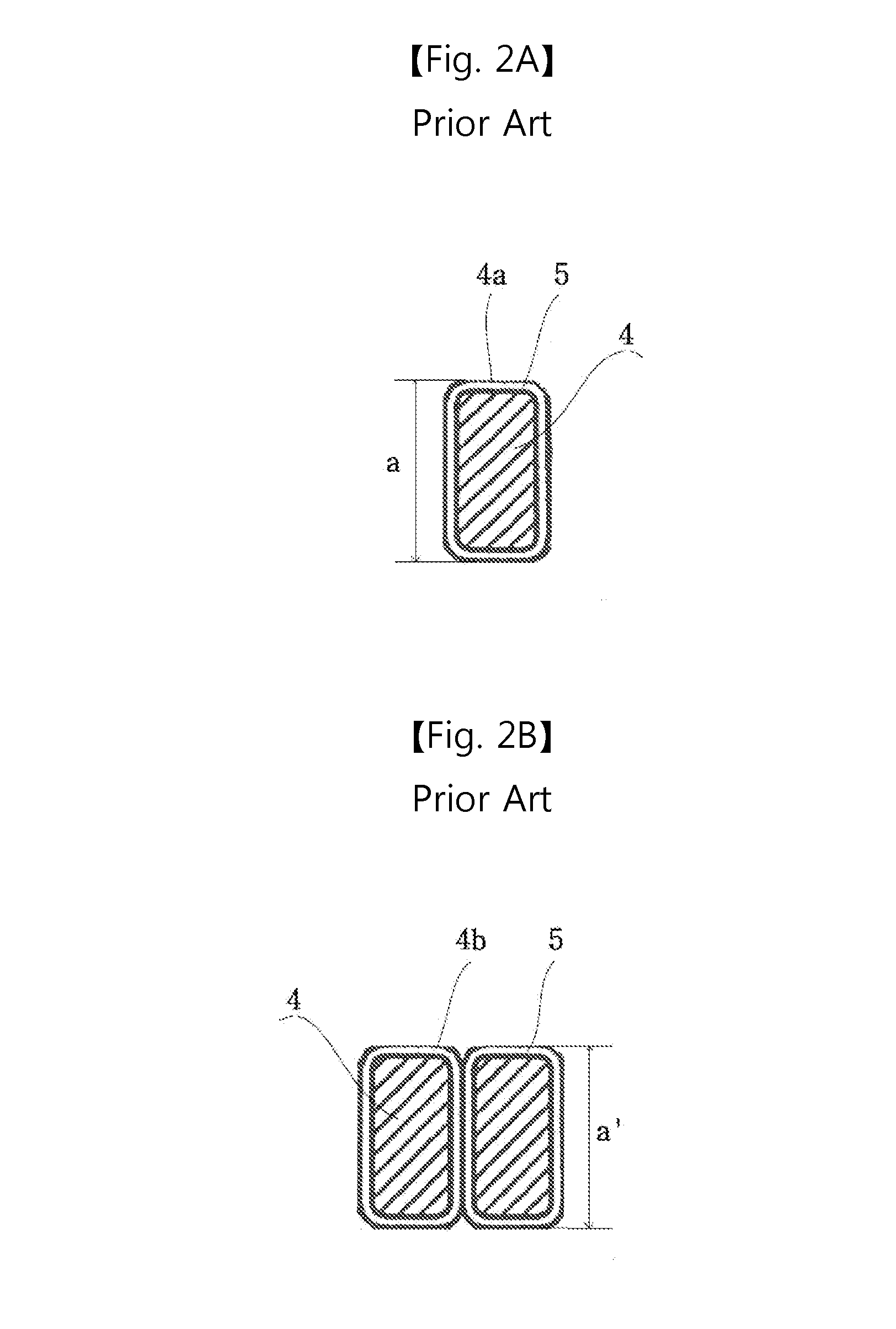
However, in the related art, a method of reducing eddy current losses by adjusting a dimension of a coil conductor has a drawback which is difficult to apply for maintaining mechanical strength.

Method used


Image

  • Transformer for reducing eddy current losses of coil
  • Transformer for reducing eddy current losses of coil
  • Transformer for reducing eddy current losses of coil

Examples


Embodiment Construction

[0033]Description will now be given in detail of the exemplary embodiments, with reference to the accompanying drawings. For the sake of brief description with reference to the drawings, the same or equivalent components will be provided with the same reference numbers, and description thereof will not be repeated.

[0034]Hereinafter, preferred embodiments of the present invention will be described in detail with reference to the accompanying drawings. However, the embodiments are provided only to disclose the invention in a manner sufficiently clear and complete for the invention to be easily carried out by a person having ordinary skill in the art to which the invention pertains, but do not mean to limit technical ideas and categories of the present invention.

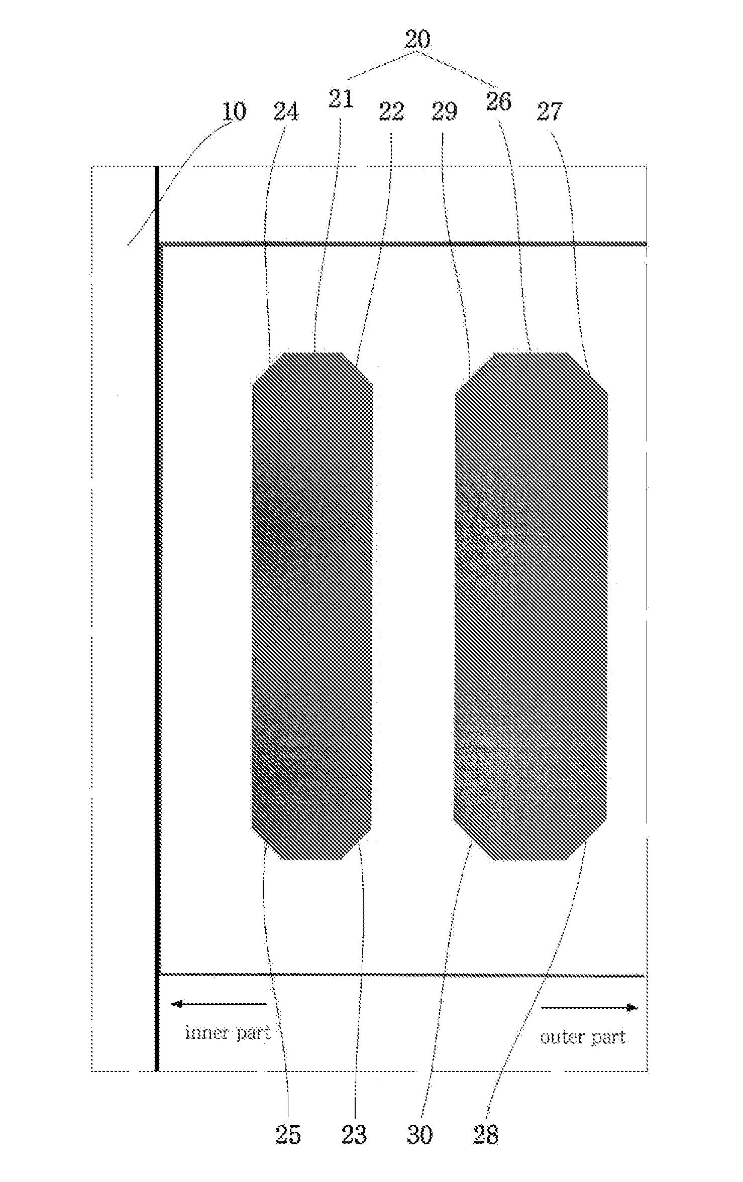
[0035]FIG. 5 is a schematic diagram illustrating cross-sectional surfaces of a core and a coil of a transformer according to an exemplary embodiment of the present invention. The transformer for reducing eddy current losses of ...


PUM

PropertyMeasurementUnit
eddy current lossesaaaaaaaaaa
insulatingaaaaaaaaaa
lengthaaaaaaaaaa

Abstract

Disclosed is a transformer for reducing eddy current losses of a coil, in which a cut part which is provided by removing a portion of a conductor is provided in each of an upper end and a lower end of a coil, and thus, eddy current losses caused by leakage flux are reduced. The transformer includes a core and a first coil and a second coil sequentially installed on a concentric circle to surround the core. A cut part which is provided by removing a portion of a conductor is provided at each of a first outer upper end and a first outer lower end of the first coil and a second inner upper end and a second inner lower end of the second coil to reduce an influence of leakage flux.

Description

CROSS-REFERENCE TO RELATED APPLICATION[0001]Pursuant to 35 U.S.C. §119(a), this application claims the benefit of earlier filing date and right of priority to Korean Patent Application No. 10-2015-0025969, filed on Feb. 24, 2015, the contents of which is incorporated by reference herein in its entirety.BACKGROUND OF THE DISCLOSURE[0002]1. Field of the Disclosure[0003]The present disclosure relates to a transformer for reducing eddy current losses of a coil, and particularly, to a transformer in which a cut part which is provided by removing a portion of a conductor is provided in each of an upper end and a lower end of a coil, and thus, eddy current losses caused by leakage flux are reduced.[0004]2. Background of the Disclosure[0005]Generally, a high voltage power transformer is an electronic device that is provided in a power system and is supplied with a voltage from a power station to boost and lower the voltage. The high voltage power transformer plays an important role in trans...

Claims


Application Information

Patent Timeline
Patent Type & Authority Applications(United States)
IPC IPC(8): H01F27/34H01F27/24H01F27/28
CPCH01F27/346H01F27/2823H01F27/28H01F2027/348H01F27/24H01F27/306H01F27/34H01F27/32
Inventor LEE, SEUNGWOOK
Owner LSIS CO LTD
Learn More