Rotating machine

Inactive Publication Date: 2009-04-16
HITACHI LTD
View PDF2 Cites 1 Cited by
  • Summary
  • Abstract
  • Description
  • Claims
  • Application Information

AI Technical Summary

Benefits of technology

[0009]The invention can provide a high efficiency rotating machine by reducing eddy current losses in

Problems solved by technology

However, it has a problem in that the depressions or projections radially extending from the rotation axis disturb the swirl flow

Method used


Image

  • Rotating machine
  • Rotating machine
  • Rotating machine

Examples


Embodiment Construction

[0022]A rotating machine according to a first embodiment of the invention will be described below with reference to FIGS. 1, 2 and 3.

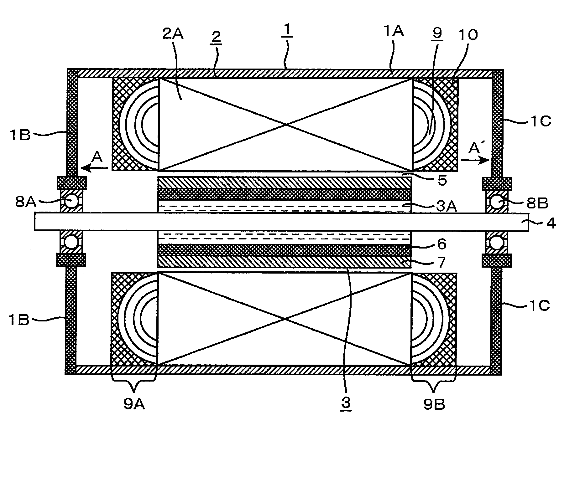
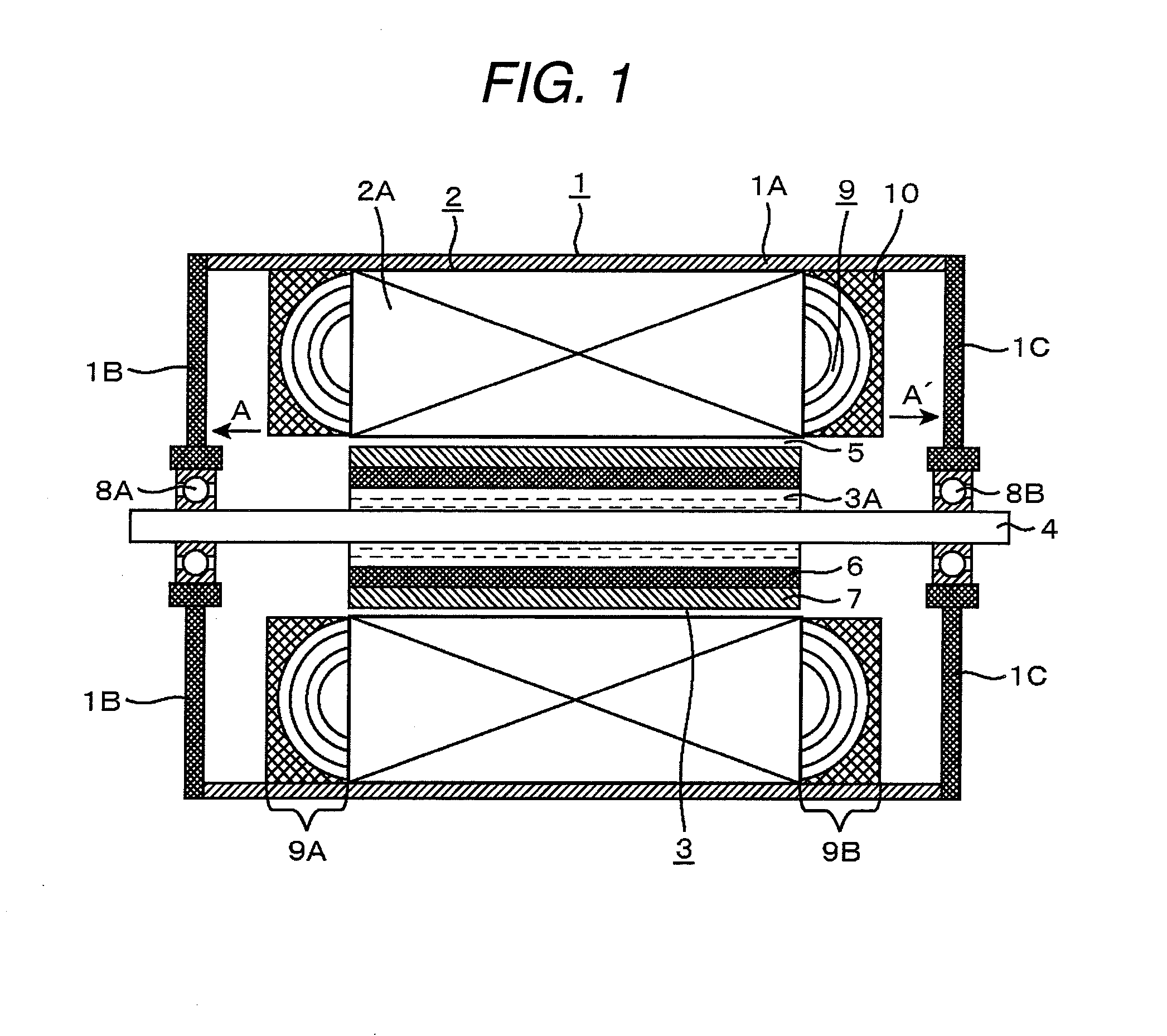
[0023]The rotating machine according to the first embodiment is a high-speed generator for use in a micro gas turbine and a permanent magnet rotating machine having permanent magnets mounted on its rotor. FIG. 1 is a schematic longitudinal sectional view of the rotating machine according to the first embodiment. This rotating machine essentially includes: a housing 1 formed by bolting (not shown) substantially disc-shaped end brackets 1B and 1C to a housing cylinder 1A; bearings 8A and 8B fixed to the housing 1 and rotatably supporting a rotary shaft 4; a rotor 3 fixed to the rotary shaft 4; and a stator 2 surrounding the rotor 3 and fixed to the housing 1 with an air gap 5 formed between the rotor 3 and stator 2. The stator 2 is formed into a cylindrical shape by laminating thin ring-like magnetic steel sheets 2A and is provided with multiple slots (n...


PUM


Abstract

There is provided a rotating machine including a stator and a rotor, in which the inner side surface (facing the stator) of the axial end structures of the stator is provided with grooves filled with an electrically nonconductive material.

Description

CLAIM OF PRIORITY[0001]The present application claims priority from Japanese patent application serial No. 2007-268495, filed on Oct. 16, 2007, the content of which is hereby incorporated by reference into this application.FIELD OF THE INVENTION[0002]The present invention relates to rotating machines, and particularly to end structures of stators.BACKGROUND OF THE INVENTION[0003]Generally, ultra-high-speed rotating machines (typified by generators for micro gas-turbine systems) are designed to increase the critical speed by decreasing the bearing span of the rotor. A generator rotor in such ultra-high-speed rotating machines is directly connected to the turbine or compressor. So, the axial end portions of the generator are designed compactly and the end brackets are disposed close to the coil ends. Here, the term “coil end” refers to a coil portion positioned on an axial end of a stator (or rotor) core, where a coil side inserted in one slot is connected to another coil side in anot...

Claims


Application Information

Patent Timeline
IPC IPC(8): H02K1/12
CPCH02K5/04H02K5/08H02K2205/12H02K15/026H02K11/0005H02K11/012
Inventor SASAKI, MANABUMIKAMI, HIROYUKIKISHIBE, TADAHARU
Owner HITACHI LTD
Why Eureka
Try Eureka