Method of annealing amorphous ribbons and marker for electronic article surveillance
What is Al technical title?
Al technical title is built by PatSnap Al team. It summarizes the technical point description of the patent document.
a technology of amorphous ribbons and markers, applied in the field of magnetic amorphous alloys, can solve the problems of enhanced ac losses, interference with harmonic systems, and unsuitability of pulse-field magnetomechanical eas systems
Inactive Publication Date: 2006-08-03
TYCO FIRE & SECURITY GMBH
View PDF32 Cites 3 Cited by
Summary
Abstract
Description
Claims
Application Information
AI Technical Summary
This helps you quickly interpret patents by identifying the three key elements:
Problems solved by technology
Method used
Benefits of technology
[0022] It is an object of the present invention to provide a method of reducing the eddy current losses of a ferromagnetic ribbon which in operation is magnetized by a static magnetic bias field.
[0027] Another object of the present invention is to provide such an alloy which, when incorporated in a marker for a magnetomechanical surveillance system, does not trigger an alarm in a harmonic surveillance system.
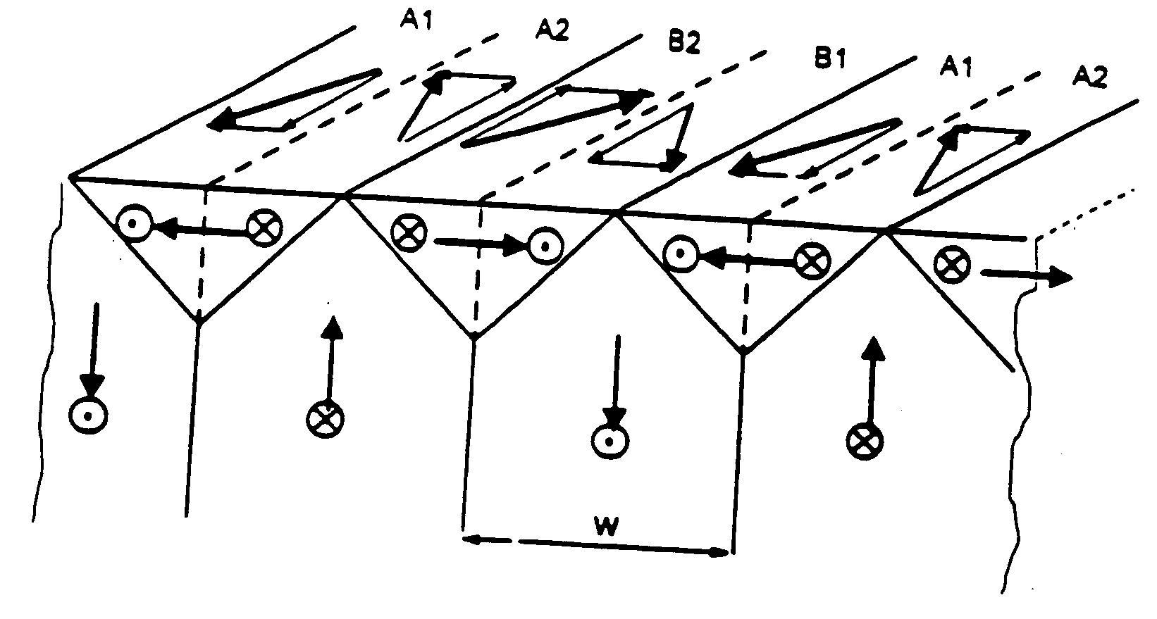
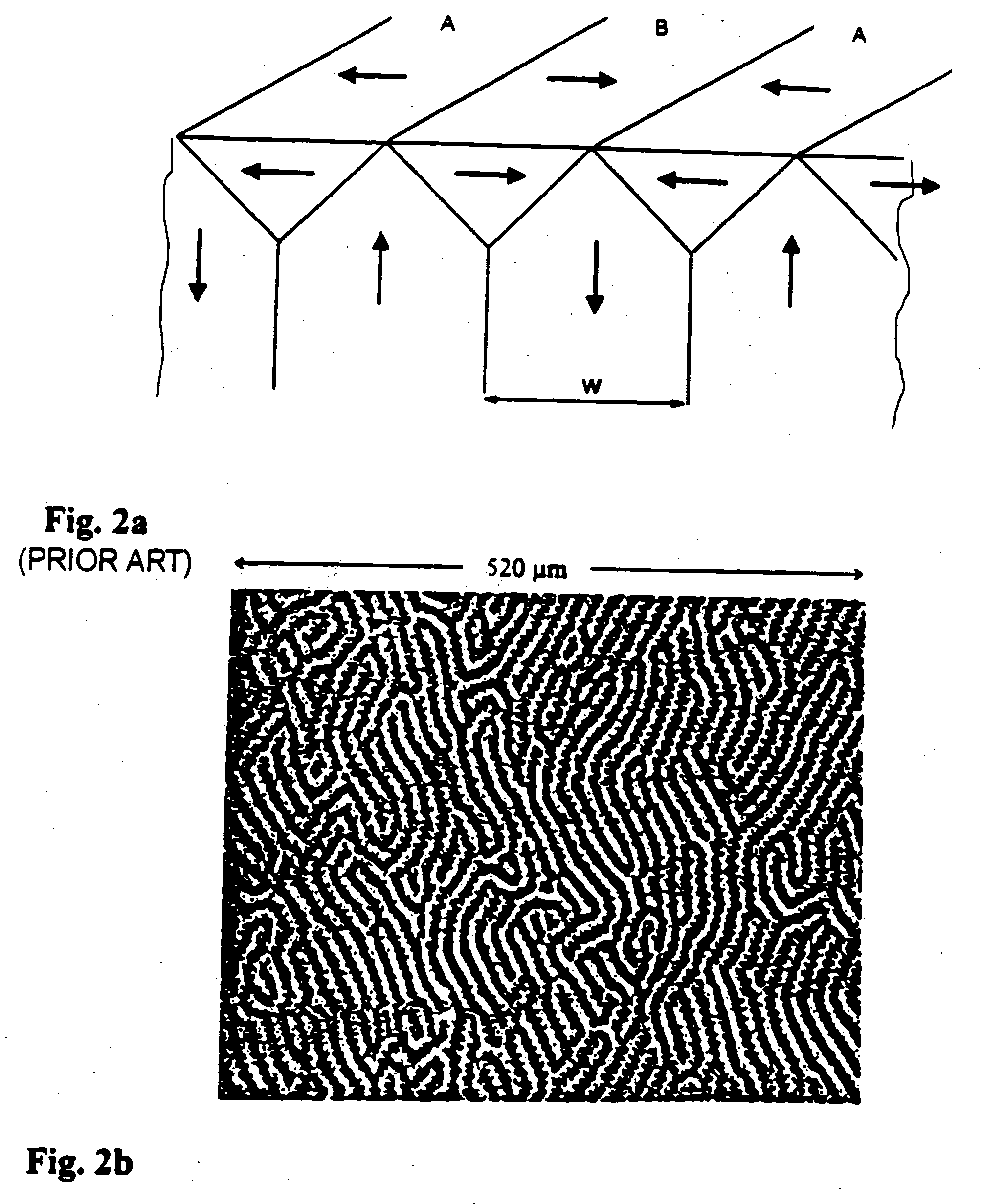
[0030] The above objects are achieved in a resonator, a marker embodying such a resonator and a magnetomechanical article surveillance system employing such a marker, wherein the resonator is an amorphous magnetostrictive alloy and wherein the raw amorphous magnetostrictive alloy is annealed in a such a way that a fine domain structure is formed with a domain width less than about 40 μm and that an anisotropy is induced which is perpendicular to the ribbon axis and points out of the ribbon plane at an angle larger than 5° up to 90° with respect to the ribbon plane. The lower bound for the anisotropy angle is necessary to achieve the desired refinement of the domain structure which is necessary to reduce eddy current losses, and thus improves the signal amplitude, and hence improves the performance of the electronic article surveillance system using such a marker.
[0042] Additionally, the reduction of eddy current losses by means of the heat treatment described herein can be of benefit for non-magneto-elastic applications and can enhance the performance of a near-zero magnetostrictive Co-based alloy when used e.g. in toroidally wound cores operated with a pre-magnetization generated by a DC current.
Problems solved by technology
Such interference with harmonic systems actually is a severe problem with the aforementioned magneto-elastic markers of the prior art, due the non-linear hysteresis loop typical associated with the as prepared state of amorphous alloys, since it is this non-linear behavior which (undesirably) triggers an alarm in a harmonic EAS system.
This patent also teaches that a preferred material is an Fe—Co alloy which contains at least about 30 at % Co, whereas earlier materials of the prior art such as Fe40Ni38Mo3B18, disclosed in the aforementioned PCT Application WO 90 / 03652 are unsuitable in pulse-field magnetomechanical EAS systems since annealing such materials undesirably reduces the ring down period of the signal.
The result was a relatively linear magnetization loop but again with a non-linear opening in its center region and enhanced AC losses.
Method used
Image
Click on the blue label to locate the original text in one second.
Reading with bidirectional positioning of images and text.
Examples
Embodiment Construction
Alloy Preparation
[0067] Amorphous metal alloys within the Fe—Co—Ni—Si—B system were prepared by rapidly quenching from the melt as thin ribbons typically 25 μm thick. Table I lists typical examples of the investigated compositions and their basic material parameters. All casts ere prepared from ingots of at least 3 kg using commercially available raw materials. The ribbons used for the experiments were 6 mm wide and were either directly cast to their final width or slit from wider ribbons. The ribbons were strong, hard and ductile and had a shiny top surface and a somewhat less shiny bottom surface.
TABLE IExamples of the investigated alloy compositions and their magneticproperties. Js is the saturation magnetization, λs the saturationmagnetostriction constant and Tc is the Curie temperature. The Curietemperature of alloys 8 and 9 is higher than crystallization temperature ofthese samples (=440° C.) and, thus, could not be measured.Alloyatomic constituents (at %)magnetic properti...
PUM
Property
Measurement
Unit
magnetization
aaaaa
aaaaa
width
aaaaa
aaaaa
domain width
aaaaa
aaaaa
Abstract
A ferromagnetic resonator for use in a marker in a magnetomechanical electronic article surveillance system has improved magnetoresonant properties and / or reduced eddy current losses by virtue of being annealed so that the resonator has a fine domain structure with a domain width less than about 40 ÿm, or less than about 1.5 times the thickness of the resonator. This produces in the resonator an induced magnetic easy axis which is substantially perpendicular to the axis along which the resonator is operated magnetically by a magnetic bias element also contained in the marker. The annealing which produces these characteristics can take place in a magnetic field of at least 1000 Oe, oriented at an angle with respect to the plane of the material being annealed so that the magnetic field has a significant component perpendicular to this plane, a component of at least about 20 Oe across the width of the material, and a smallest component along the direction of transport of the material through the annealing oven.
Description
[0001] The present application is a divisional application of Ser. No. 10 / 830,576, filed Apr. 23, 2004, which is a divisional of Ser. No. 10 / 358,950, filed Feb. 5, 2003 (abandoned), which is a divisional application of Ser. No. 09 / 703,913, filed Nov. 1, 2000, which issued as U.S. Pat. No. 6,551,416, which is a divisional application of Ser. No. 09 / 262,689, filed Mar. 4, 1999, which issued as U.S. Pat. No. 6,299,702, which is a divisional application of Ser. No. 08 / 968,653, filed Nov. 12, 1997, which issued as U.S. Pat. No. 6,011,475.BACKGROUND OF THE INVENTION [0002] 1. Field of the Invention [0003] The present invention relates to magnetic amorphous alloys and to a method of annealing these alloys in a magnetic field. The present invention is also directed to amorphous magnetostrictive alloys for use in a magnetomechanical electronic article surveillance system. The present invention furthermore is directed to a magnetomechanical electronic article surveillance system employing suc...
Claims
Application Information
Patent Timeline
Application Date:The date an application was filed.
Publication Date:The date a patent or application was officially published.
First Publication Date:The earliest publication date of a patent with the same application number.
Issue Date:Publication date of the patent grant document.
PCT Entry Date:The Entry date of PCT National Phase.
Estimated Expiry Date:The statutory expiry date of a patent right according to the Patent Law, and it is the longest term of protection that the patent right can achieve without the termination of the patent right due to other reasons(Term extension factor has been taken into account ).
Invalid Date:Actual expiry date is based on effective date or publication date of legal transaction data of invalid patent.
Patent Type & Authority Applications(United States)