High-Q Integrated Inductor and Method Thereof

a high-q integrated inductor and high-q technology, applied in the direction of transformer/inductance details, inductance, inductance/transformer/magnet manufacturing, etc., can solve the problem of reducing the magnetic field coupling between the coil and the shielding structure, reducing the energy loss of itself, and reducing the q factor

Active Publication Date: 2019-10-31
REALTEK SEMICON CORP
View PDF0 Cites 0 Cited by
  • Summary
  • Abstract
  • Description
  • Claims
  • Application Information

AI Technical Summary

Benefits of technology

[0002]A conventional integrated inductor comprises a coil laid out on a metal layer secured by a dielectric slab attached on a substrate. A high Q factor is usually highly desirable for an integrated inductor, as it is a measure of how effectively the integrated inductor preserves energy. A substrate loss usually leads to appreciable energy loss and thus degradation of the Q factor. The substrate loss includes both Ohmic loss and Eddy current loss. The Ohmic loss results from an electric field coupling between the coil and the substrate, while the Eddy current loss results from a magnetic field coupling. A shielding structure can be inserted between the coil and the substrate on another metal layer housed by the dielectric slab to reduce electric and / or magnetic field coupling and thus substrate loss. However, the shielding structure itself could lead to energy loss of itself. To prevent Eddy current loss on the shielding structure of itself, the shielding structure is often configured to be perpendicular to the integrated inductor as seen from a top view. This arrangement greatly reduces magnetic field coupling between the coil and the shielding structure and thus the Eddy current loss on the shielding structure, but provides almost no help in reducing the magnetic field coupling between the coil and the substrate. Therefore, the shielding structure provides almost no help in reducing the Eddy current loss in the substrate.

Problems solved by technology
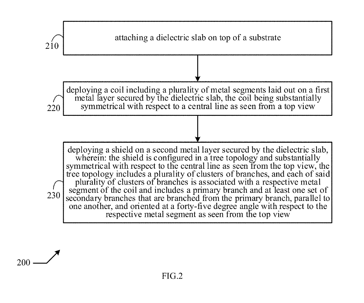
A substrate loss usually leads to appreciable energy loss and thus degradation of the Q factor.
However, the shielding structure itself could lead to energy loss of itself.
This arrangement greatly reduces magnetic field coupling between the coil and the shielding structure and thus the Eddy current loss on the shielding structure, but provides almost no help in reducing the magnetic field coupling between the coil and the substrate.
Therefore, the shielding structure provides almost no help in reducing the Eddy current loss in the substrate.

Method used


Image

  • High-Q Integrated Inductor and Method Thereof
  • High-Q Integrated Inductor and Method Thereof

Examples


Embodiment Construction

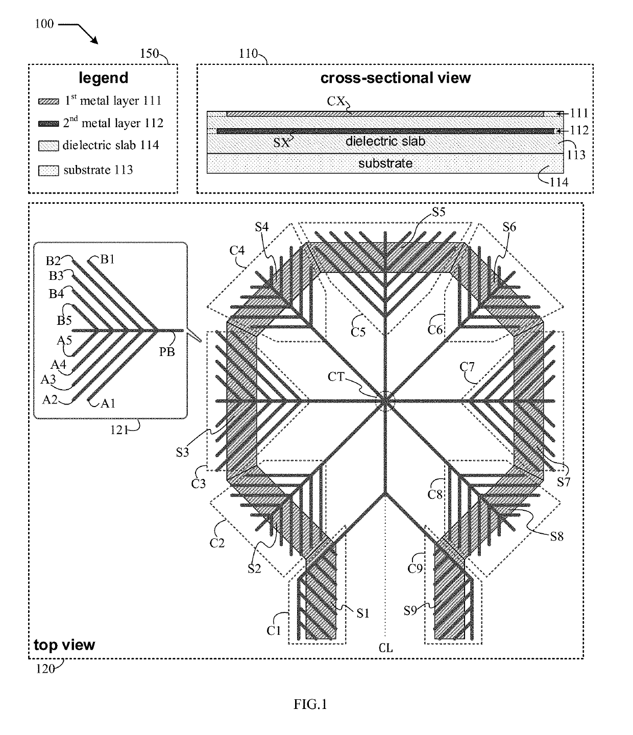
[0008]The present disclosure is directed to integrated inductors. While the specification describes several example embodiments of the disclosure considered favorable modes of practicing the invention, it will be understood by persons skilled in the art that the invention can be implemented in many ways and is not limited to the particular examples described below or to the particular manner in which any features of such examples are implemented. In other instances, well-known details are not shown or described to avoid obscuring aspects of the disclosure.

[0009]Persons of ordinary skill in the art understand terms and basic concepts related to microelectronics that are used in this disclosure, such as “substrate,”“dielectric slab,”“inductor,”“electric field coupling,”“magnetic field coupling,”“current,”“voltage,”“Ohmic loss,”“Eddy current,”“AC (alternate current) ground,”“differential signaling.” Terms and basic concepts like these are apparent to those of ordinary skill in the art ...


PUM

PropertyMeasurementUnit
degree angleaaaaaaaaaa
energy lossaaaaaaaaaa
Eddy current lossaaaaaaaaaa

Abstract

A device having a substrate, a dielectric slab attached upon the substrate, a coil including a plurality of metal segments laid out on a first metal layer secured by the dielectric slab, the coil being substantially laterally symmetrical with respect to a central line from a top view perspective, and a shield laid out on a second metal layer secured by the dielectric slab and configured in a tree topology. The shield is substantially laterally symmetrical with respect to the central line from the top view perspective, the tree topology including a plurality of clusters of branches, wherein each of said plurality of clusters of branches is associated with a respective metal segment of the coil and includes a primary branch and at least one set of secondary branches that are branched from the primary branch, parallel to one another, and oriented at a substantially forty-five-degree angle with respect to the respective metal segment from the top view perspective.

Description

BACKGROUND OF THE DISCLOSUREField of the Disclosure[0001]The present disclosure generally relates to integrated inductors, and more particularly to integrated inductors having a high quality factor (Q factor).Description of Related Art[0002]A conventional integrated inductor comprises a coil laid out on a metal layer secured by a dielectric slab attached on a substrate. A high Q factor is usually highly desirable for an integrated inductor, as it is a measure of how effectively the integrated inductor preserves energy. A substrate loss usually leads to appreciable energy loss and thus degradation of the Q factor. The substrate loss includes both Ohmic loss and Eddy current loss. The Ohmic loss results from an electric field coupling between the coil and the substrate, while the Eddy current loss results from a magnetic field coupling. A shielding structure can be inserted between the coil and the substrate on another metal layer housed by the dielectric slab to reduce electric and / o...

Claims


Application Information

Patent Timeline
Patent Type & Authority Applications(United States)
IPC IPC(8): H01F17/00H01F41/04
CPCH01F17/0013H01F2017/0053H01F2017/0073H01F41/041H01F2017/008H01F2017/0086H01F27/34H01F27/36H01F2027/348H01L28/10H01F17/0006
Inventor LIN, CHIA-LIANG (LEON)WU, I-CHANGSONG, FEI
Owner REALTEK SEMICON CORP
Why Eureka
Try Eureka