Transverse flux switched reluctance motor and control methods

a technology of switching resistance and switching resistance, applied in the direction of electronic commutation motor control, motor/generator/converter stopper, dynamo-electric converter control, etc., can solve the problems of poor magnetic properties, limiting the use of smc material, and inconvenient use, so as to eliminate end turn losses and improve the density of winding coils. , the effect of cost-effectiveness

Inactive Publication Date: 2006-05-04
PRECISE AUTOMATION
View PDF38 Cites 52 Cited by
  • Summary
  • Abstract
  • Description
  • Claims
  • Application Information

AI Technical Summary

Benefits of technology

[0011] As has been appreciated by the inventor, the advent of a new material, a “soft magnetic composite” or “SMC,” has allowed the design of cost-effective new motor topologies that can eliminate end turn losses and greatly improve the density of the winding coil (the winding “fill factor”). SMC material allows the magnetic flux to efficiently travel in 3 dimensions and opens up new design possibilities. This material is available as an iron powder whose particles are coated with a thin layer of plastic so that the material is magnetically permeable, but is electrically insulating so as to prevent eddy current losses. SMC powder allows precision geometries to be created by compressing the material to form a part of a desired shape, thereby eliminating costly machining operations.

Problems solved by technology

However, SMC material is not without its drawbacks.
The first generation of this class of material, which was offered by several manufacturers in the mid 1990s, was extremely fragile and had relatively poor magnetic properties, greatly limiting its use.
The permeability of second generation SMC materials, while improved, was still lower than in conventional motor lamination material such as, for example M19, such that motors would exhibit thermal problems in higher torque applications due to the high currents necessary to drive sufficient flux through the relatively low permeability SMC material.
In addition, SMC material has higher AC core losses than commonly used motor lamination material, resulting in higher motor heating than with conventional lamination materials such as, for example M19.

Method used


Image

  • Transverse flux switched reluctance motor and control methods
  • Transverse flux switched reluctance motor and control methods
  • Transverse flux switched reluctance motor and control methods

Examples


Embodiment Construction

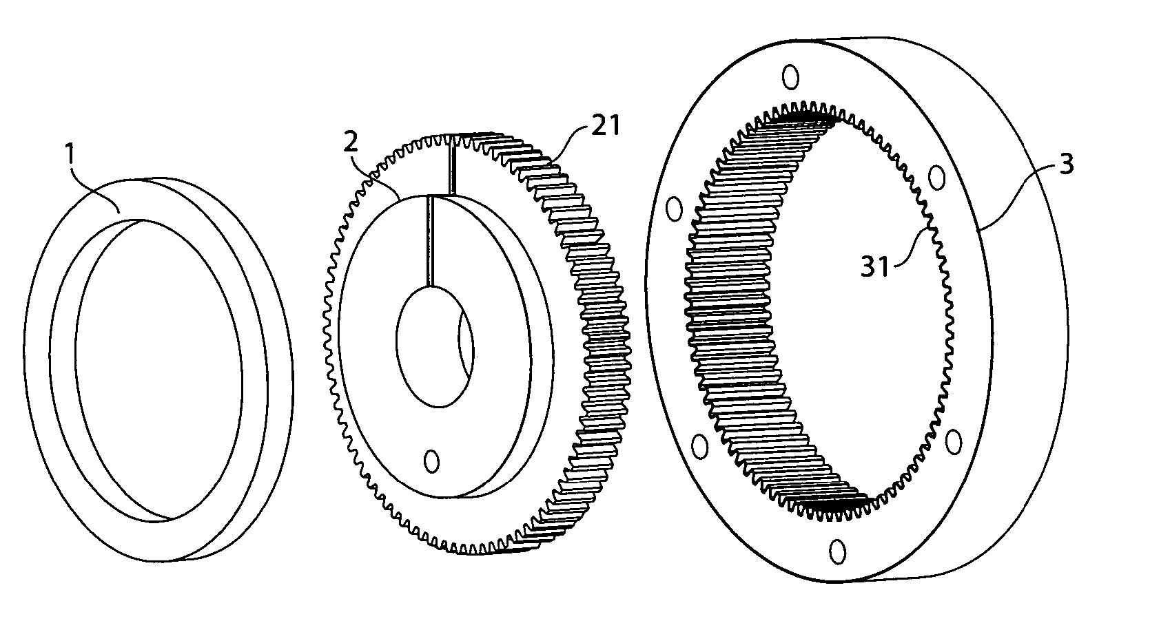
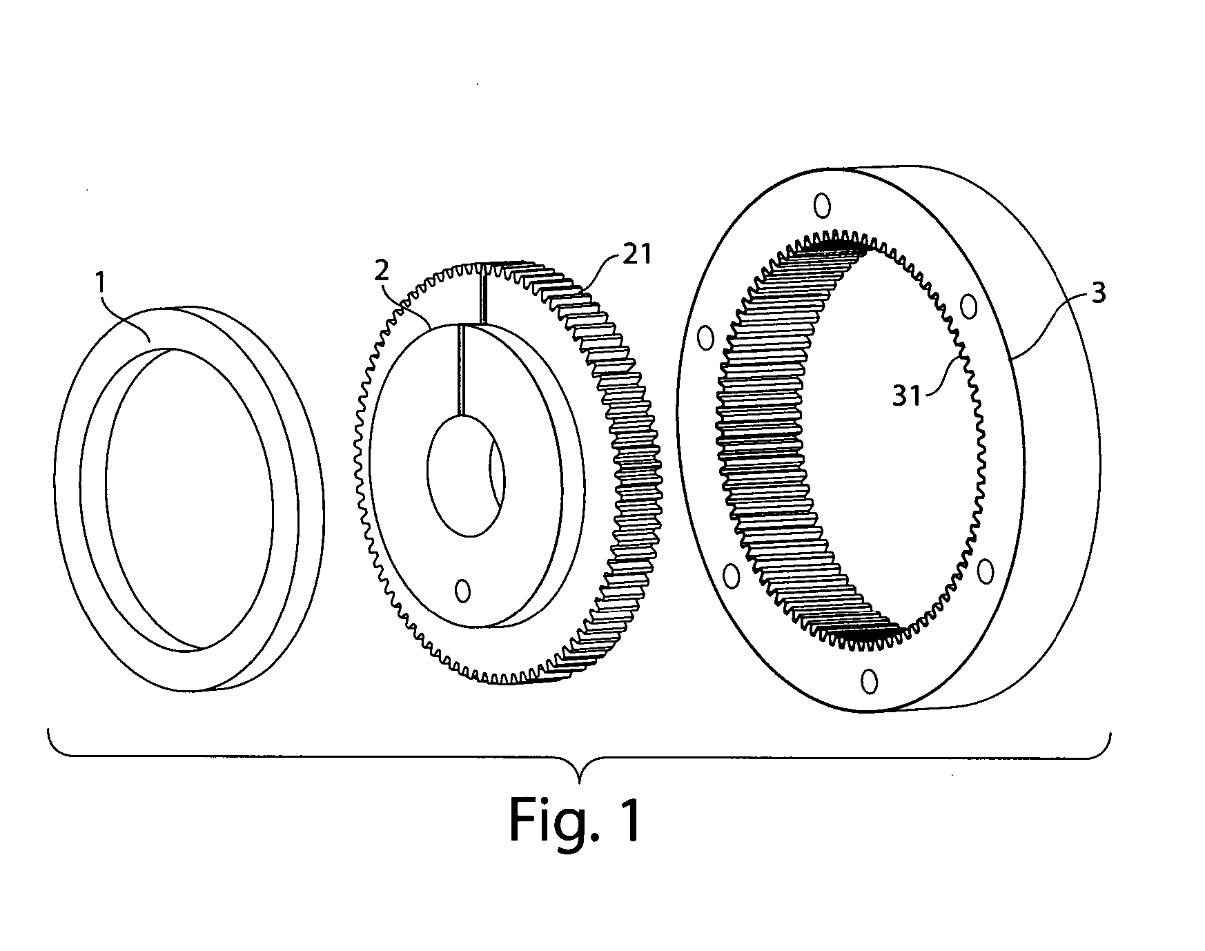
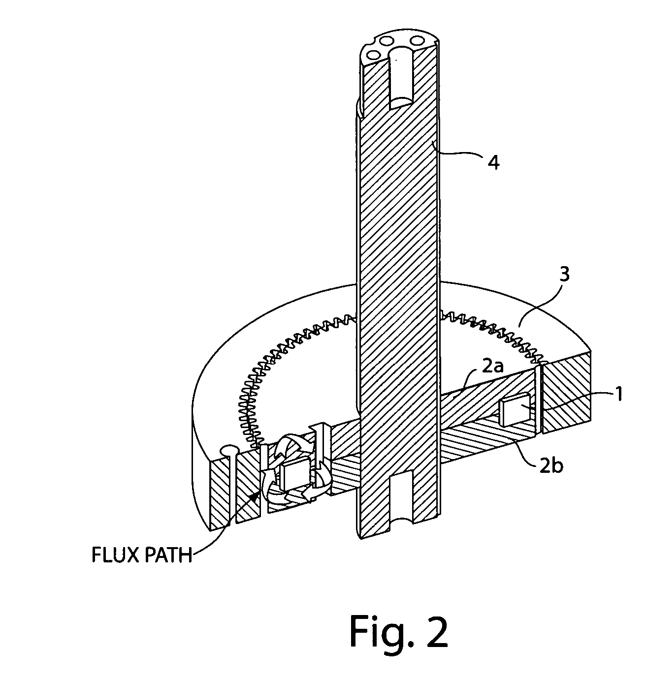
[0032] Various aspects of the invention are described below with reference to illustrative embodiments. However, it should be understood that aspects of the invention are not limited to those embodiments described below, but instead may be used in any suitable system or arrangement. For example, an illustrative embodiment is described below in which motor phases include rotors positioned around a stator and arranged to rotate. It should be understood, however, that motor phases may include an internally positioned rotor that rotates within a stator. Also, although a coil with each motor phase is shown associated with the stator, the coil may be associated with the rotor. Other variations will be appreciated by those of skill in the art and are consistent with various aspect of the invention.

[0033]FIGS. 1 and 2 show an illustrative embodiment of a motor phase in accordance with the invention. The motor phase in this illustrative embodiment is composed of only 3 different parts, a co...


PUM


Abstract

A variable reluctance motor and methods for control. The motor may include N motor phases, where N equals three or more. Each motor phase may include a coil to generate a magnetic flux, a stator and a rotor. A flux-carrying element for the rotor and/or stator may be made entirely of SMC. The stators and rotors of the N motor phases may be arranged relative to each other so that when the stator and rotor teeth of a selected phase are aligned, the stator and rotor teeth in each of the other motor phases are offset from each other, e.g., by an integer multiple of 1/N of a pitch of the stator or rotor teeth. A fill factor of the coil relative to the space in which it is housed may be at least 60%, and up to 90% or more. The stator and rotor flux-carrying elements together may include at most three separable parts.

Description

BACKGROUND OF INVENTION [0001] Aspects of the invention relate to variable reluctance, or switched reluctance, motors and methods for control of such motors. [0002] Many electric drive applications require high rotary torque or linear thrust at relatively low speeds. To generate this power, a transmission or speed reducer is often interposed between a high-speed power source and the output shaft. This transmission is almost always mechanical in nature, with costly highly loaded components that are subject to wear over time. This wear results in lost precision of motion, which is undesirable and limits both the life and the capability of the power source. [0003] As a result, there has recently been increased interest in direct-drive electric motors for both rotary and linear applications. These motors are designed to generate high torque or thrust at relatively low speeds, thereby eliminating the need for a speed reducer between the motor and the load. [0004] Many such motors have be...

Claims


Application Information

Patent Timeline
Patent Type & Authority Applications(United States)
IPC IPC(8): H02K19/00H02K19/20
CPCH02K19/103H02K19/18H02K21/12H02K21/125H02K21/24
Inventor CARLISLE, BRIAN R.
Owner PRECISE AUTOMATION
Why Eureka
Try Eureka