
Transistor body control circuit and an integrated circuit

a technology of integrated circuits and control circuits, applied in the direction of diodes, electronic switching, pulse techniques, etc., can solve the problems of unidirectional devices, high manufacturing costs, and large area occupied on circuit boards

Active Publication Date: 2016-08-25
NXP USA INC
View PDF0 Cites 26 Cited by
  • Summary
  • Abstract
  • Description
  • Claims
  • Application Information

AI Technical Summary

Benefits of technology

The invention described here has several benefits. The technical effects of the invention include improved efficiency, reduced energy consumption, and better performance. These benefits make it easier to use the invention and get the most out of it.

Problems solved by technology

However, standard power transistors have no technically meaningful blocking voltage in one direction, making them unidirectional devices.
The separate MOSFETs are formed on separate semiconductor dice, and often housed in separate packages, which results in a high manufacturing cost and a large area occupied on a circuit board.
When the separate MOSFET dice are housed in a single package and interconnected with wire bonds, the area occupied on a circuit board is reduced but the manufacturing cost is still too high for many applications.
However, this bi-directional trench power transistor has an inherent parasitic bipolar transistor formed by the body and the high voltage regions.
Furthermore, it is not suitable for operation with high voltages, such as of at least 20 or more, e.g. up to 40 V or more, and / or high currents, e.g. above 1 mA, up to 1 A or more.
However, this bias switch comes with a risk of over-voltages damaging the MOSFETs since the gates of the MOSFETs are connected directly to the drain and source respectively.
Accordingly, in case the maximum drain-source voltages of the bidirectional transistor exceed the breakdown voltages of the MOSFETs the latter risk irreversible damage.

Method used


Image

  • Transistor body control circuit and an integrated circuit
  • Transistor body control circuit and an integrated circuit
  • Transistor body control circuit and an integrated circuit

Examples


Embodiment Construction

[0017]Because the illustrated embodiments of the present invention can for the most part, be implemented using electronic components and circuits known to those skilled in the art, details will not be explained in any greater extent than that considered necessary as illustrated for the understanding and appreciation of the underlying concepts of the present invention and in order not to obfuscate or distract from the teachings of the present invention.

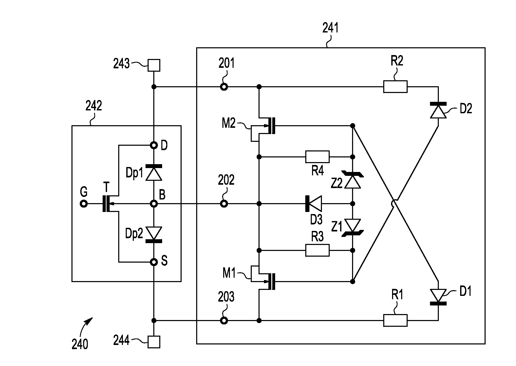
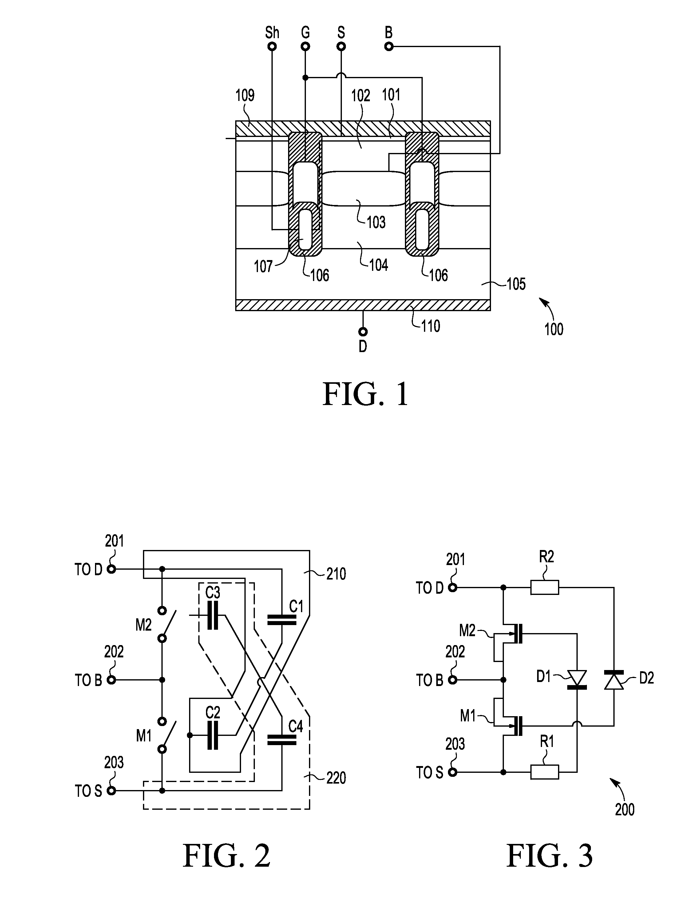
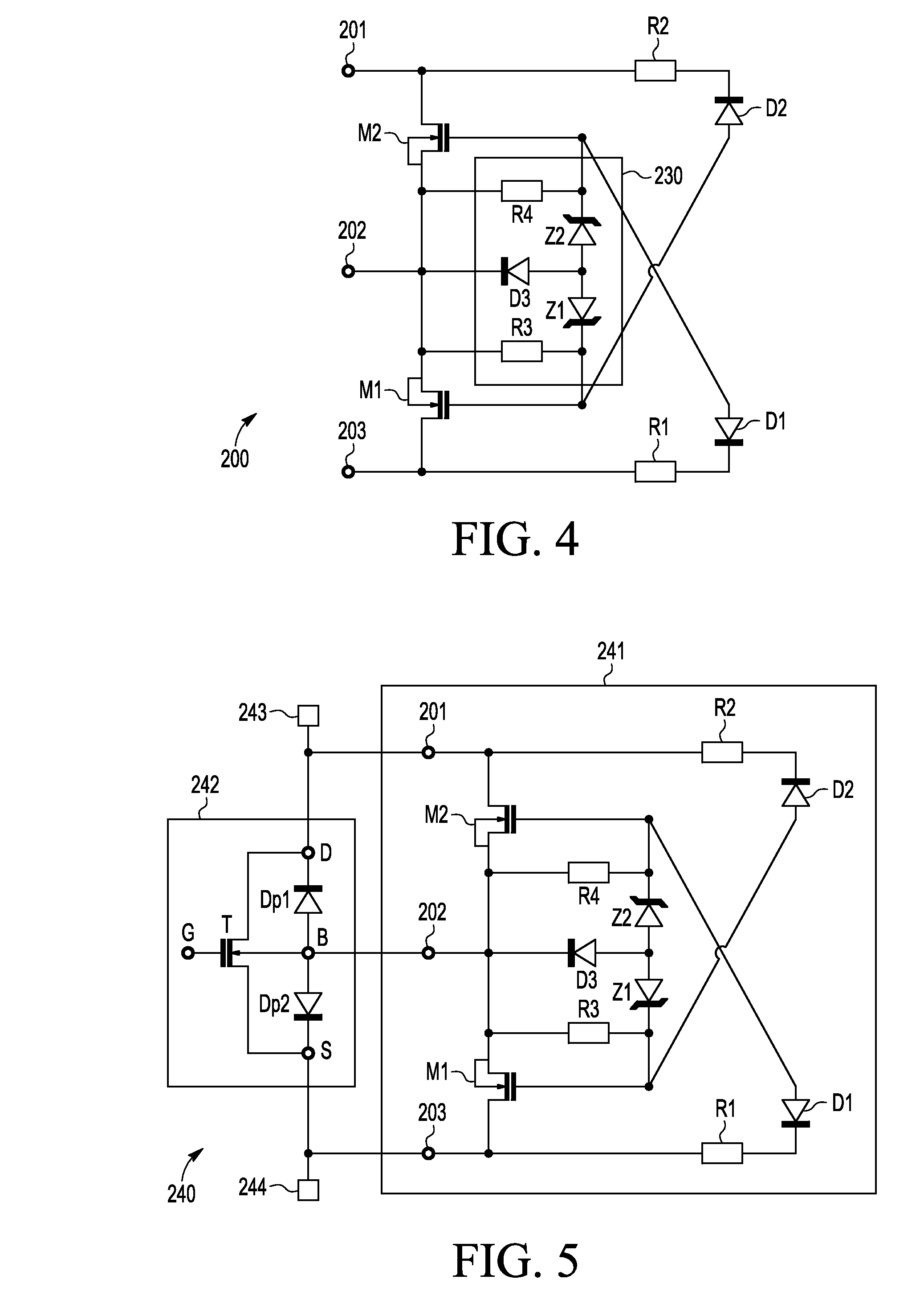
[0018]FIG. 1 shows an example of a bidirectional power transistor 100. The power transistor 100 shown in FIG. 1 is a bi-directional transistor, as is explained below in more detail, which can support high energies, i.e. high currents and / or voltages both from the source towards the drain and vice-versa and. The power transistor can for example have a current maximum of more than 1 A, such as 10 A or more, such as 100 A or more, such as at least 200 A and / or a positive drain-source break down voltage of at least 25 V, for example 50 V o...


PUM


Abstract

An integrated circuit comprises a transistor body control circuit for controlling a body of a bidirectional power transistor. The transistor body control circuit comprises switches connected between a body terminal and a first current terminal, with a control terminal for controlling the current flowing through the switch.The control terminal of the switch is connected to alternating current, AC capacitive voltage divider. The AC capacitive voltage dividers are connected to the control terminals and arranged to control the switches to switch the voltage of the body terminal as a function of the voltage between the first current terminal and the second current terminal. The integrated circuit further comprises a bi-directional power transistor connected to the transistor body control circuit.

Description

FIELD OF THE INVENTION[0001]This invention relates to a transistor body control circuit and an integrated circuit.BACKGROUND OF THE INVENTION[0002]Bi-directional switches switch high currents through their conduction electrodes while blocking high voltages applied to the conduction electrodes. Bi-directional switches are used in a variety of electrical systems. A typical bi-directional switch is specified to supply high currents, which can range from several Amperes of maximum current to several hundreds of Amperes depending on the specific switch and application, while blocking relatively high voltages, e.g. of at least 25 V without breaking down.[0003]Bi-directional switches are typically implemented using electromechanical switches or a configuration of semiconductor devices, e.g. power transistors. However, standard power transistors have no technically meaningful blocking voltage in one direction, making them unidirectional devices. Consequently, current bi-directional switches...

Claims


Application Information

Patent Timeline
Patent Type & Authority Applications(United States)
IPC IPC(8): H01L27/07H01L29/78H03K17/687
CPCH01L27/0727H01L29/7827H03K17/687H03K2217/0018H03K17/102H03K2217/0009H01L27/0629H01L27/02H03K17/08H01L29/407H01L29/7813H01L29/086
Inventor STAFANOV, EVGUENIYDE FRESART, EDOUARD DENISGRANDRY, HUBERT MICHEL
Owner NXP USA INC
Learn More