Backlight module for liquid crystal display and liquid crystal display device

Inactive Publication Date: 2016-08-25
TCL CHINA STAR OPTOELECTRONICS TECH CO LTD
View PDF4 Cites 2 Cited by
  • Summary
  • Abstract
  • Description
  • Claims
  • Application Information

AI Technical Summary

Benefits of technology

[0017]Compared with the light source circuit of the backlight module in the prior art, in the light source circuit of the backlight module according to the present disclosure, the light-emitting units can be controlled separately. In this case, when it is not necessary to activate all light-emitting units according to actual needs of the liquid crystal display device, the light-emitting units which are necessary can be activated by the control circuit, while the light-emitting units which are not necessary can be deactivated by the control circuit. Since it is not necessary to activate all light-emitting units, the power consumption of the backlight module can be reduced effectively, and thus the life time of the electric devices (such as mobile phones) can be prolonged.
[0018]In addition, in the light source circuit according to the present disclosure, the brightness of the light source can also be regulated. Specifically, the time period during which the controllable switch is turned on or turned off can be regulated thro

Problems solved by technology

With the development of liquid crystal display technology, the size of the liquid crystal display devices that are used in mobile phones is becoming increasingly large, which renders that the power consumption of the liquid crysta

Method used


Image

  • Backlight module for liquid crystal display and liquid crystal display device
  • Backlight module for liquid crystal display and liquid crystal display device
  • Backlight module for liquid crystal display and liquid crystal display device

Examples


third embodiment

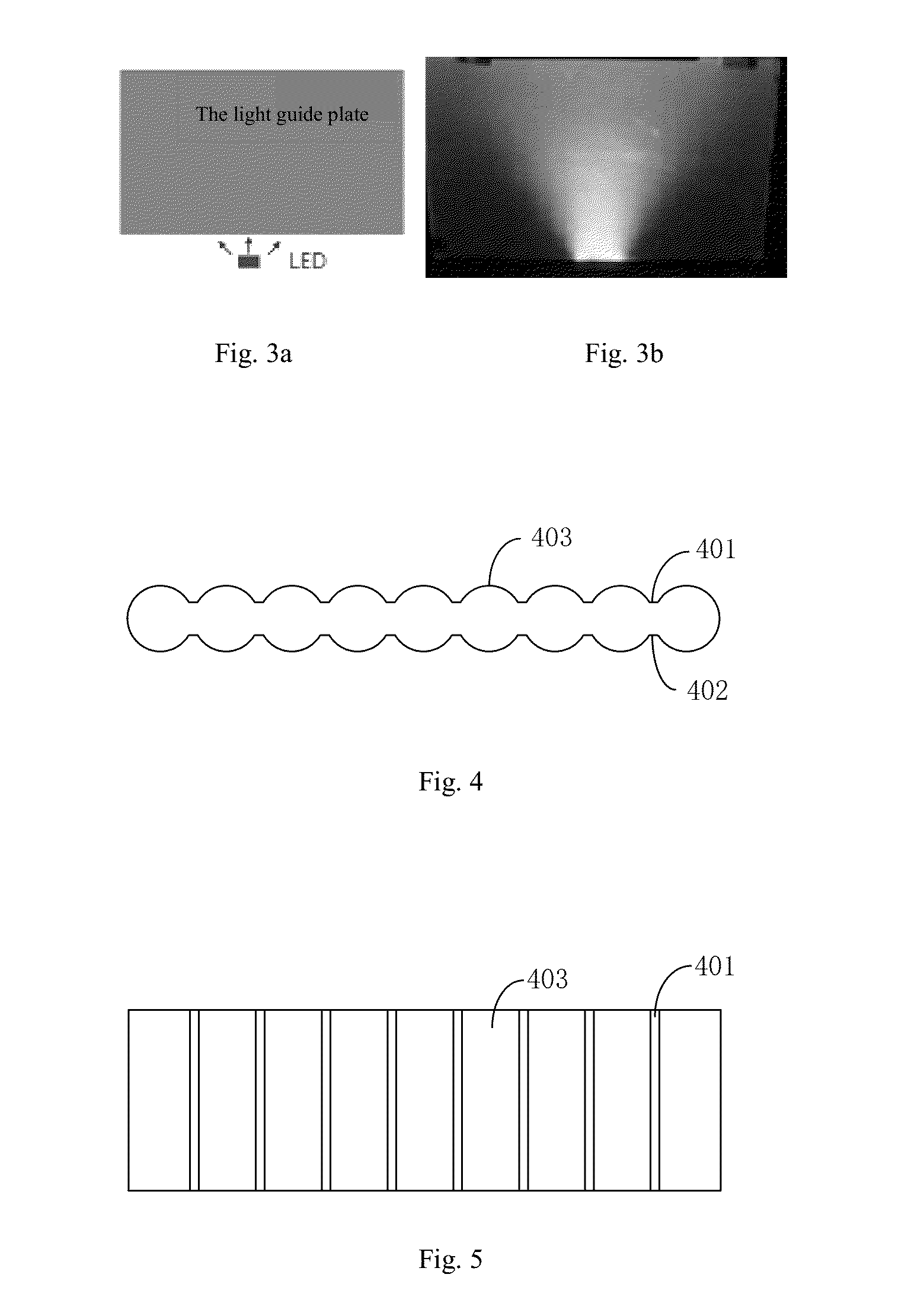
[0067]According to the present disclosure, the light guide plate can have a structure as shown in FIG. 14. It can be seen that, compared with the light guide plate as shown in FIG. 4, the light guide plate is only provided with cylindrical protrusions on the first surface, while the second surface still has a plane structure. According to the present embodiment, the light guide apertures are all arranged on the second surface. This is because, the second surface has a plane structure, and it is easy to form light guide apertures in the plane structure (for example, the light guide apertures can be formed through wet etching). However, it is hard to form light guide apertures in the cylindrical protrusions on the first surface (the light guide apertures are usually formed through laser etching), and the producing difficulty and cost of the light guide plate would be improved apparently. Of course, the light guide apertures can also be formed in the cylindrical protrusions on the firs...

fourth embodiment

[0068]According to the present disclosure, the light guide plate can have a structure as shown in FIG. 15. It can be seen in combination with FIG. 14 that, the light guide plate as shown in FIG. 15, in addition to the situation that no distance is arranged between the adjacent cylindrical protrusions of the light guide plate, has the same structure as the light guide plate as shown in FIG. 14, the details of which are no longer repeated here.

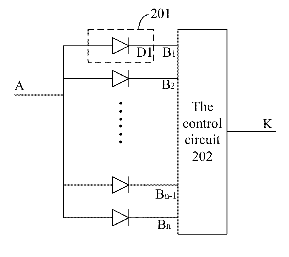
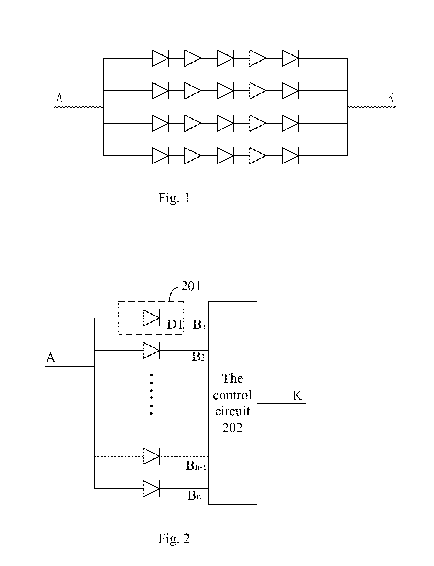
[0069]Compared with the light source circuit of the backlight module in the prior art, in the light source circuit of the backlight module according to the present disclosure, the light-emitting units can be controlled separately. In this case, when it is not necessary to activate all light-emitting units according to actual needs of the liquid crystal display device, the light-emitting units which are necessary can be activated by the control circuit, while the light-emitting units which are not necessary can be deactivated by the control circu...


PUM


Abstract

A backlight module for liquid crystal display device and a liquid crystal display device are disclosed. The backlight module comprises a light source circuit and a light guide plate, wherein said light source circuit comprises a control circuit and a plurality of light-emitting units, which are arranged on a lateral surface of said light guide plate and connected with said control circuit, each light-emitting unit being activated or deactivated by said control circuit; and wherein said light guide plate is used for guiding light which enters from the lateral surface, so that the light exits from a front surface. The power consumption of the backlight module according to the present disclosure is lower than the light source circuit of the backlight module in the prior art.

Description

CROSS REFERENCE TO RELATED APPLICATION[0001]The present application claims benefit of Chinese patent application CN 201410856635.1, entitled “Backlight Module for Liquid Crystal Display and Liquid Crystal Display Device” and filed on Dec. 31, 2014, which is incorporated herein by reference.FIELD OF THE INVENTION[0002]The present disclosure relates to the technical field of liquid crystal display, and particularly to a backlight module for liquid crystal display device and a liquid crystal display device.BACKGROUND OF THE INVENTION[0003]With the development of mobile technology, mobile phones have become indispensable communication tools in people's daily life. At present, Liquid Crystal Display (LCD) devices are most widely used as the screens of mobile phones. The liquid crystal display technology has undergone the development from black-and-white screen to colored screen, as well as from Twisted Nematic LCD (TN-LCD) to Thin Film Transistor LCD (TFT-LCD).[0004]With the development ...

Claims


Application Information

Patent Timeline
IPC IPC(8): H05B33/08F21V8/00H05B44/00
CPCG02B6/00G09G3/34H05B33/0815G02B6/0068G02B6/0045G09G3/3406G09G3/3413G02F1/133612G09G3/342G09G2320/064G09G2330/021G02B6/0036G02B6/0038H05B45/00H05B45/10
Inventor ZHENG, YINGBO
Owner TCL CHINA STAR OPTOELECTRONICS TECH CO LTD
Why Eureka
Try Eureka