Cleaning device having a nozzle for cleaning a surface

a cleaning device and cleaning nozzle technology, which is applied in the direction of vacuum cleaners, carpet cleaners, floor sweeping machines, etc., can solve the problems of dirt particles scattered in the housing in unpredictable ways, dirt particles are not picked up, and the vacuuming effect is not good, so as to improve the cleaning effect and speed up the removal of liquid. , the effect of increasing the capillary force of the brush

Active Publication Date: 2016-09-08
VERSUNI HLDG BV
View PDF7 Cites 9 Cited by
  • Summary
  • Abstract
  • Description
  • Claims
  • Application Information

AI Technical Summary

Benefits of technology

[0086]A deformation of the brush elements, or, to say it more accurately, a speed at which deformation can take place, is also influenced by the linear mass density of the brush elements. Furthermore, the linear mass density of the brush elements influences the power which is needed for rotating the brush. When the linear mass density of the brush elements is relatively low, the flexibility is relatively high, and the power needed for causing the brush elements to bend when they come into contact with the surface to be cleaned or with the first deflection surface is relatively low. This also means that a friction power which is generated between the brush elements and the floor or the first deflection surface is low, whereby any damages are prevented. Other advantageous effects of a relatively low linear mass density of the brush elements are a relatively high resistance to wear, a relatively small chance of damage by sharp objects or the like, and the capability to follow the surface to be cleaned in such a way that contact is maintained even when a substantial unevenness in the floor is encountered.
[0087]A factor which may play an additional role in the cleaning function of the rotatable brush is a packing density of the brush elements. When the packing density is large enough, capillary effects may occur between the brush elements, which enhance fast removal of liquid from the surface to be cleaned. According to an embodiment of the present invention the packing density of the brush elements is at least 30 tufts of brush elements per cm2, wherein a number of brush elements per tuft is at least 500.
[0088]Arranging the brush elements in tufts forms additional capillary channels, thereby increasing the capillary forces of the brush for picking-up dirt particles and liquid droplets from the surface to be cleaned.
[0089]As it has been mentioned above, the presented cleaning device has the ability to realize extremely good cleaning results. These cleaning results can be even improved by actively wetting the surface to be cleaned. This is especially advantageous in case of stain removal. The liquid used in the process of enhancing adherence of dirt particles to the brush elements may be provided in various ways. In a first place, the rotatable brush and the flexible brush elements may be wetted by a liquid which is present on the surface to be cleaned. An example of such a liquid is water, or a mixture of water and soap. Alternatively, a liquid may be provided to the flexible brush elements by actively supplying the cleansing liquid to the brush, for example, by oozing the liquid onto the brush, or by injecting the liquid into a hollow core element of the brush.
[0090]According to an embodiment, it is therefore preferred that the cleaning device comprises means for supplying a liquid to the brush at a rate which is lower than 6 ml per minute per cm of a width of the brush in which the brush axis is extending. It appears that it is not necessary for the supply of liquid to take place at a higher rate, and that the above-mentioned rate suffices for the liquid to fulfill a function as a carrying / transporting means for dirt particles. Thus, the ability of removing stains from the surface to be cleaned can be significantly improved. An advantage of only using a little liquid is that it is possible to treat delicate surfaces, even surfaces which are indicated as being sensitive to a liquid such as water. Furthermore, at a given size of a reservoir containing the liquid to be supplied to the brush, an autonomy time is longer, i.e. it takes more time before the reservoir is empty and needs to be filled again.
[0091]It has to be noted that, instead of using an intentionally chosen and actively supplied liquid, it is also possible to use a spilled liquid, i.e. a liquid which is to be removed from the surface to be cleaned. Examples are spilled coffee, milk, tea, or the like. This is possible in view of the fact that the brush elements, as mentioned before, are capable of removing the liquid from the surface to be cleaned, and that the liquid can be removed from the brush elements under the influence of centrifugal forces as described in the foregoing. The above-mentioned effect of re-spraying the surface in the area between the brush and the bouncing surface of the first deflector element may be overcome by the first deflector element which collects this re-sprayed liquid and dirt by acting as kind of wiper (in the forward stroke), so that remaining liquid and dirt may then be ingested if an under-pressure is applied using an additional vacuum aggregate.

Problems solved by technology

In current single rotating wet brush floor cleaning devices it is an issue that dirt particles are not picked up by the vacuum air flow but get launched across the floor.
This leads to a disposal of the dirt across the floor but not to the actually intended cleaning of the floor.
The problem is that by using rotating brushes the dirt particles are scattered within the housing in an unpredictable way.
Especially at high rotation speeds of the brush the trajectory of the dirt particles bouncing forth and back between the brush and the interior of the housing is most of the time completely random and therefore unpredictable.
However, it is evident that such large vacuum aggregates are not only cost-intensive, but also consume a lot of energy.
Apart from that large vacuum aggregates are quite noisy.
Experiments of the applicant have shown that even if powerful vacuum aggregates are used, the problem of unintentionally dispersing the dirt with the brush over the floor may not be completely overcome.
In most known cleaning devices according to the prior art the dirt particles are scattered within the interior of the nozzle in such an uncontrolled manner that not all dirt particles are directly guided into the nozzle outlet.
In case of cleaning devices with a single rotating brush this often results in the fact that the dirt particles that have been picked up by the brush will make a further turn with the brush, which throws them back onto the floor again.
Especially when the exhaust is not able to catch (suck) the dirt particles away from the brush and into the nozzle outlet, the brush may take the dirt particles back to the floor again.
It is evident that this does not lead to a satisfactory cleaning result.
First of all, the construction including the two delimiting elements is rather complicated and interference-prone.
Therefore, large vacuum aggregates need to be used which again result in a high consumer price of the device.
Apart from that, this device does also not solve the problem that the dirt particles are scattered in an uncontrollable manner and may get launched back to the floor.
Similar as explained above it seems problematic to guide the dirt particles in a more or less controlled manner away from the brush and into the nozzle outlet.

Method used


Image

  • Cleaning device having a nozzle for cleaning a surface
  • Cleaning device having a nozzle for cleaning a surface
  • Cleaning device having a nozzle for cleaning a surface

Examples


first embodiment

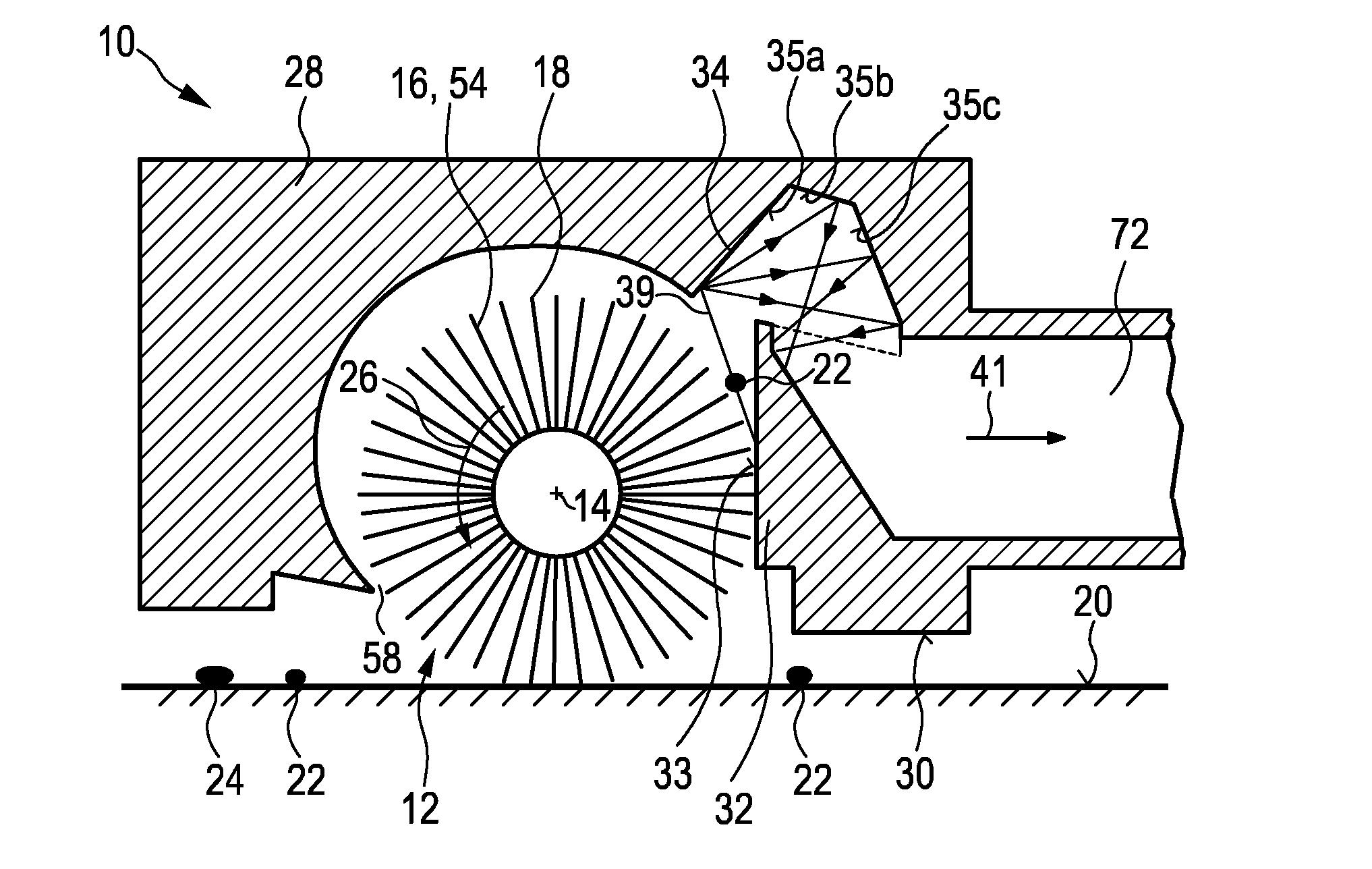
[0105]FIG. 1 shows a schematic cross-section of a nozzle arrangement 10 of a cleaning according to the present invention. The nozzle arrangement 10 comprises a brush 12 that is rotatable about a brush axis 14. Said brush 12 is provided with flexible brush elements 16 which are preferably realized by thin microfiber hairs. The flexible brush element 16 comprises tip portions 18 which are adapted to contact a surface to be cleaned 20 during the rotation of the brush and to pick-up dirt particles 22 and / or liquid particles 24 from said surface 20 (floor 20) during a pick-up period when the brush elements 16 contact the surface 20.

[0106]Further, the nozzle arrangement 10 comprises a drive means, e.g. a motor (not shown) for driving the brush 12 in a predetermined direction of rotation 26. Said drive means are preferably adapted to realize a centrifugal acceleration at the tip portions 18 of the brush elements 16 which is, in particular during a dirt release period when the brush element...

second embodiment

[0128]FIG. 6 shows the second deflector element 34 according to the present invention. In contrast to the embodiment shown in FIGS. 5a and 5b, the second deflector surface 35′ has a rounded shape. The second deflector surface 35′ is designed as a curved surface that faces into the exhaust channel 41. Similar as before, the shape of this curved surface 35′ is configured to guide the dirt and / or liquid particles 22, 24 that are released from the brush 12 at the first deflector surface 33 into the exhaust channel 41. An exemplary trajectory 39f is shown to illustrate that such a curved surface 35′ causes a very similar deflection behavior of the dirt particles 22 as the planar deflector surfaces 35a-c.

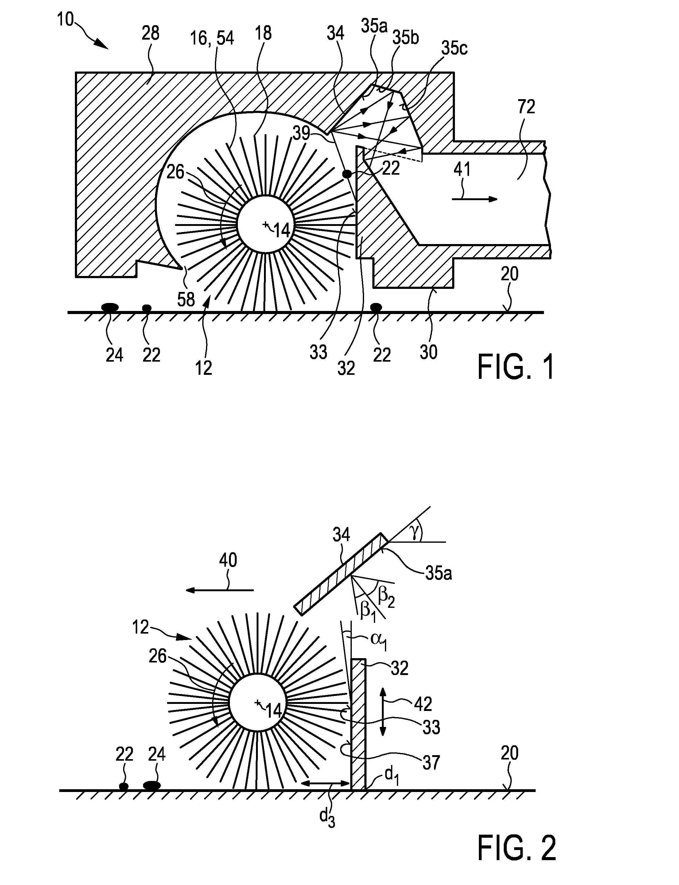
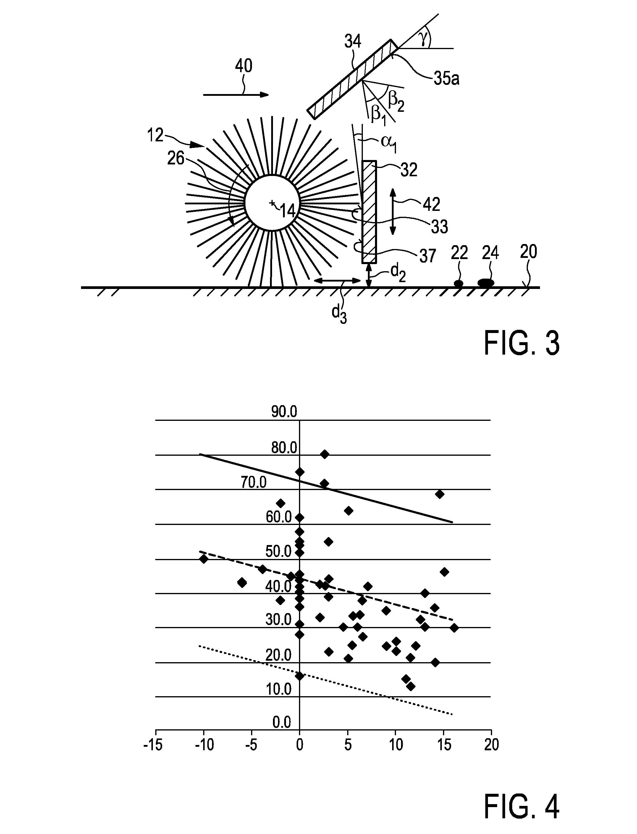
[0129]FIGS. 2 and 3 illustrate a further function of the first deflector element 32. The first deflector element 32 also has the function to act as a so-called bouncing element. It ensures that dirt and / or liquid particles 22, 24, which are already released from the brush 12 as soon as t...


PUM


Abstract

Cleaning device for cleaning a surface (20), the cleaning device having a nozzle arrangement (10) comprising: —a brush (12) rotatable about a brush axis (14), said brush (12) being provided with brush elements (16) having tip portions (18) for contacting the surface to be cleaned (20) and picking up dirt and / or liquid particles (22, 24) from the surface (20) during the rotation of the brush (12), —a drive means for rotating the brush (12), —a first deflector element (32) with a first deflector surface (33) that extends substantially parallel to the brush axis (14), wherein the first deflector surface (33) is configured to interact with the brush (12) during the rotation of the brush (12) for releasing the picked-up dirt and / or the liquid particles (22, 24) from the brush (12), and —a second deflector element (34) that is spaced apart from the brush (12) and the first deflector element (32), the second deflector element (34) comprising a second deflector surface (35a) that is oriented transverse to the first deflector surface (33), wherein the second deflector surface (35a) is configured to deflect the dirt and / or liquid particles (22, 24), which are released from the brush (12) at the first deflector surface (33), into an exhaust channel (41) that begins between the first and second deflector elements.

Description

FIELD OF THE INVENTION[0001]The present invention relates to a cleaning device for cleaning a surface. Further, the present invention relates to a nozzle arrangement for such a cleaning device.BACKGROUND OF THE INVENTION[0002]Hard floor cleaning these days is done by first vacuuming the floor, followed by mopping it. Vacuuming removes the coarse dirt, while mopping removes the stains. From the state of the art many appliances, especially targeting the professional cleaning sector, are known that claim to vacuum and mop in one go. Appliances for the professional cleaning sector are usually specialized for big areas and perfectly flat floors. They rely on hard brushes and suction power to get water and dirt from the floor. Appliances for home use often use a combination of a hard brush and a double-squeegee nozzle. Like the appliances for the professional sector these products use the brush to remove stains and the squeegee in combination with an under-pressure to lift the dirt from t...

Claims


Application Information

Patent Timeline
Patent Type & Authority Applications(United States)
IPC IPC(8): A47L9/04
CPCA47L9/0411A47L9/0488A47L11/24A47L11/4041A47L11/4044A47L9/04A47L9/0477
Inventor VAN DER KOOI, JOHANNES TSEARDROUMEN, BRITTLUBBERS, MATTHIJS HENDRIKUSKREBBERS, RAPLH PIERRE
Owner VERSUNI HLDG BV
Why Eureka
Try Eureka