Floor nozzle for vacuum cleaner

a vacuum cleaner and nozzle technology, applied in the field of cleaning devices, can solve the problems of high consumer price of the device, limited work capacity, and inability to meet the needs of cleaning equipment, and achieve the effects of enhancing the speed of liquid removal, high acceleration, and increasing the centrifugal acceleration at the top portions of the brush elemen

Active Publication Date: 2014-08-07
VERSUNI HLDG BV
View PDF18 Cites 16 Cited by
  • Summary
  • Abstract
  • Description
  • Claims
  • Application Information

AI Technical Summary

Benefits of technology

[0064]When brush elements come into contact with a dirt particle or liquid, or, in case an indentation of the brush with respect to the surface is set, the brush elements are bent. As soon as the brush elements with the dirt particles and liquid adhering thereto lose contact with the surface, the brush elements are straightened out, wherein especially the tip portions of the brush elements are moved with a relatively high acceleration. As a result the centrifugal acceleration at the top portions of the brush elements is increased. Hence, the liquid droplets and dirt particles adhering to the brush elements are launched from the brush elements, as it were, as the acceleration forces are higher than the adhesive forces, as this has been mentioned according to the embodiment above. The values of the acceleration forces are determined by various factors, including the deformation and the linear mass density as mentioned, but also by the speed at which the brush is driven.
[0065]A factor which may play an additional role in the cleaning function of the rotatable brush is a packing density of the brush elements. When the packing density is large enough, capillary effects may occur between the brush elements, which enhance fast removal of liquid from the surface to be cleaned. According to an embodiment of the present invention the packing density of the brush elements is at least 30 tufts of brush elements per cm2, wherein a number of brush elements per tuft is at least 500.
[0066]Arranging the brush elements in tufts forms additional capillary channels, thereby increasing the capillary forces of the brush for picking-up dirt particles and liquid droplets from the surface to be cleaned.
[0067]As it has been mentioned above, the presented cleaning device has the ability to realize extremely good cleaning results. These cleaning results can be even improved by actively wetting the surface to be cleaned. This is especially advantageous in case of stain removal. The liquid used in the process of enhancing adherence of dirt particles to the brush elements may be provided in various ways. In a first place, the rotatable brush and the flexible brush elements may be wetted by a liquid which is present on the surface to be cleaned. An example of such a liquid is water, or a mixture of water and soap. Alternatively, a liquid may be provided to the flexible brush elements by actively supplying the cleansing liquid to the brush, for example, by oozing the liquid onto the brush, or by injecting the liquid into a hollow core element of the brush.
[0068]According to an embodiment, it is therefore preferred that the cleaning device comprises means for supplying a liquid to the brush at a rate which is lower than 6 ml per minute per cm of a width of the brush in which the brush axis is extending. It appears that it is not necessary for the supply of liquid to take place at a higher rate, and that the above-mentioned rate suffices for the liquid to fulfill a function as a carrying / transporting means for dirt particles. Thus, the ability of removing stains from the surface to be cleaned can be significantly improved. An advantage of only using a little liquid is that it is possible to treat delicate surfaces, even surfaces which are indicated as being sensitive to a liquid such as water. Furthermore, at a given size of a reservoir containing the liquid to be supplied to the brush, an autonomy time is longer, i.e. it takes more time before the reservoir is empty and needs to be filled again.
[0069]It has to be noted that, instead of using an intentionally chosen and actively supplied liquid, it is also possible to use a spilled liquid, i.e. a liquid which is to be removed from the surface to be cleaned. Examples are spilled coffee, milk, tea, or the like. This is possible in view of the fact that the brush elements, as mentioned before, are capable of removing the liquid from the surface to be cleaned, and that the liquid can be removed from the brush elements under the influence of centrifugal forces as described in the foregoing. The above-mentioned effect of re-spraying the surface in the area between the brush and the bouncing element may be overcome by the bouncing element which collects this re-sprayed liquid and dirt by acting as kind of wiper (in the forward stroke), so that remaining liquid and dirt may then be ingested if an under-pressure is applied using an additional vacuum aggregate. The combination of the selected brush with the bouncing element thus results in a very good cleaning and drying effect.

Problems solved by technology

However, this concept has a major disadvantage, since dust and dirt can only enter the brush from one direction, i.e. from the opposite side of the dust pan.
This again results in a non-satisfying, limited work capability.
First of all, the construction including the two delimiting elements is rather complicated and interference-prone.
Therefore, large vacuum aggregates need to be used which again results in a high consumer price of the device.
However, in order to ingest the dirt that is lifted by the brushes, most of the devices need an external flow source, which again makes the device cost intensive.
Besides that, using two separate brushes makes the nozzle fairly bulky, which ends up in a non-satisfying liberty of action for the consumer.

Method used


Image

  • Floor nozzle for vacuum cleaner
  • Floor nozzle for vacuum cleaner
  • Floor nozzle for vacuum cleaner

Examples


first embodiment

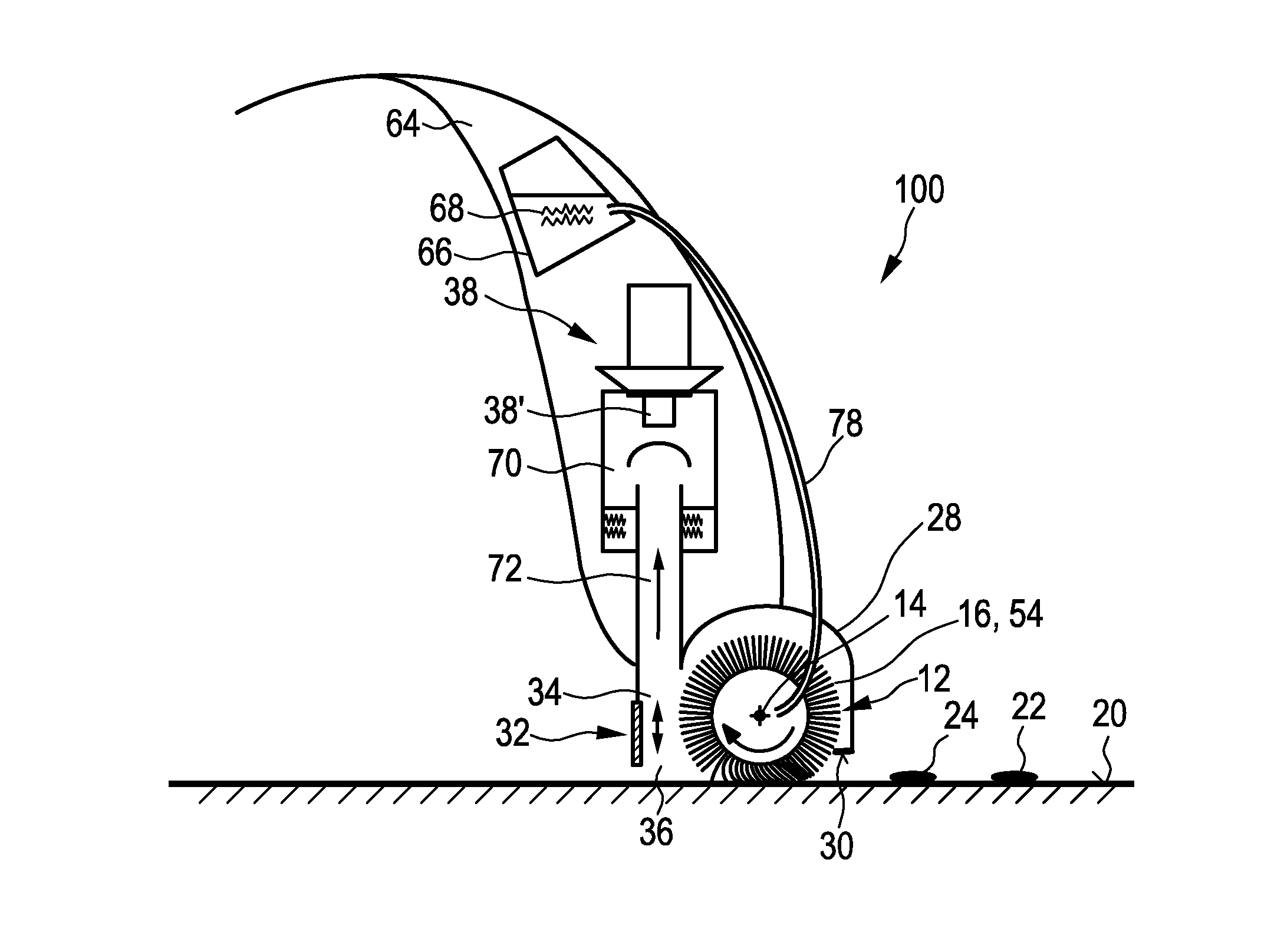
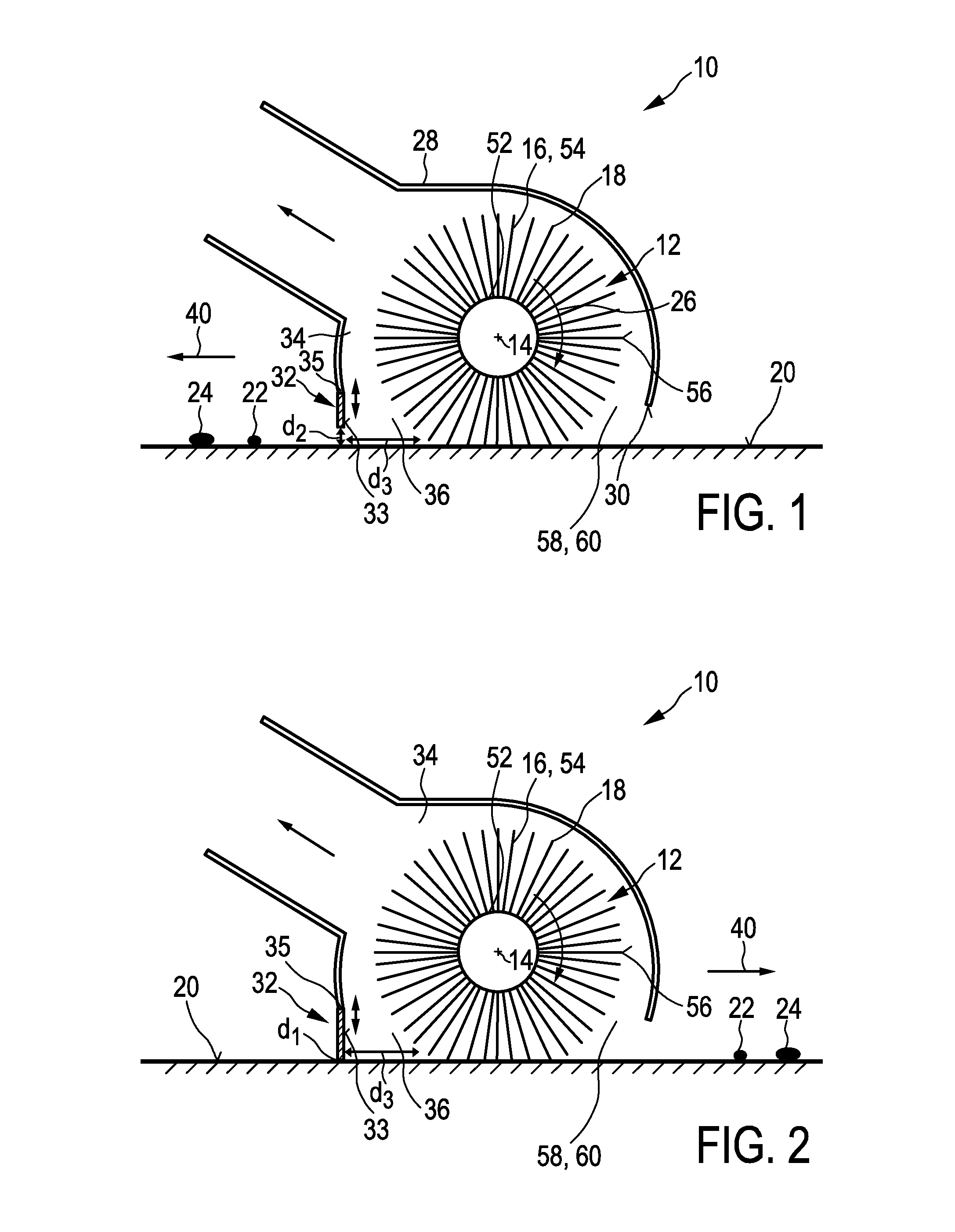
[0085]FIGS. 1 and 2 show a schematic cross-section of a nozzle arrangement 10 of a cleaning device 100 according to the present invention. In FIG. 1 the nozzle arrangement 10 is shown in a first working position, whereas in FIG. 2 the nozzle arrangement 10 is shown in a second working position. The nozzle arrangement 10 comprises a brush 12 that is rotatable about a brush axis 14. Said brush 12 is provided with flexible brush elements 16 which are preferably realized by thin microfiber hairs. The flexible brush elements 16 comprise tip portions 18 which are adapted to contact a surface to be cleaned 20 during the rotation of the brush 12 and to pick-up dirt particles 22 and / or liquid 24 from said surface 20 during a pick-up period when the brush elements 16 contact the surface 20.

[0086]A linear mass density of a majority of the brush elements 16 is, at least at their tip portions 18, preferably chosen to be lower than 150 g / 10 km. Further, the nozzle arrangement 10 comprises a drive...

second embodiment

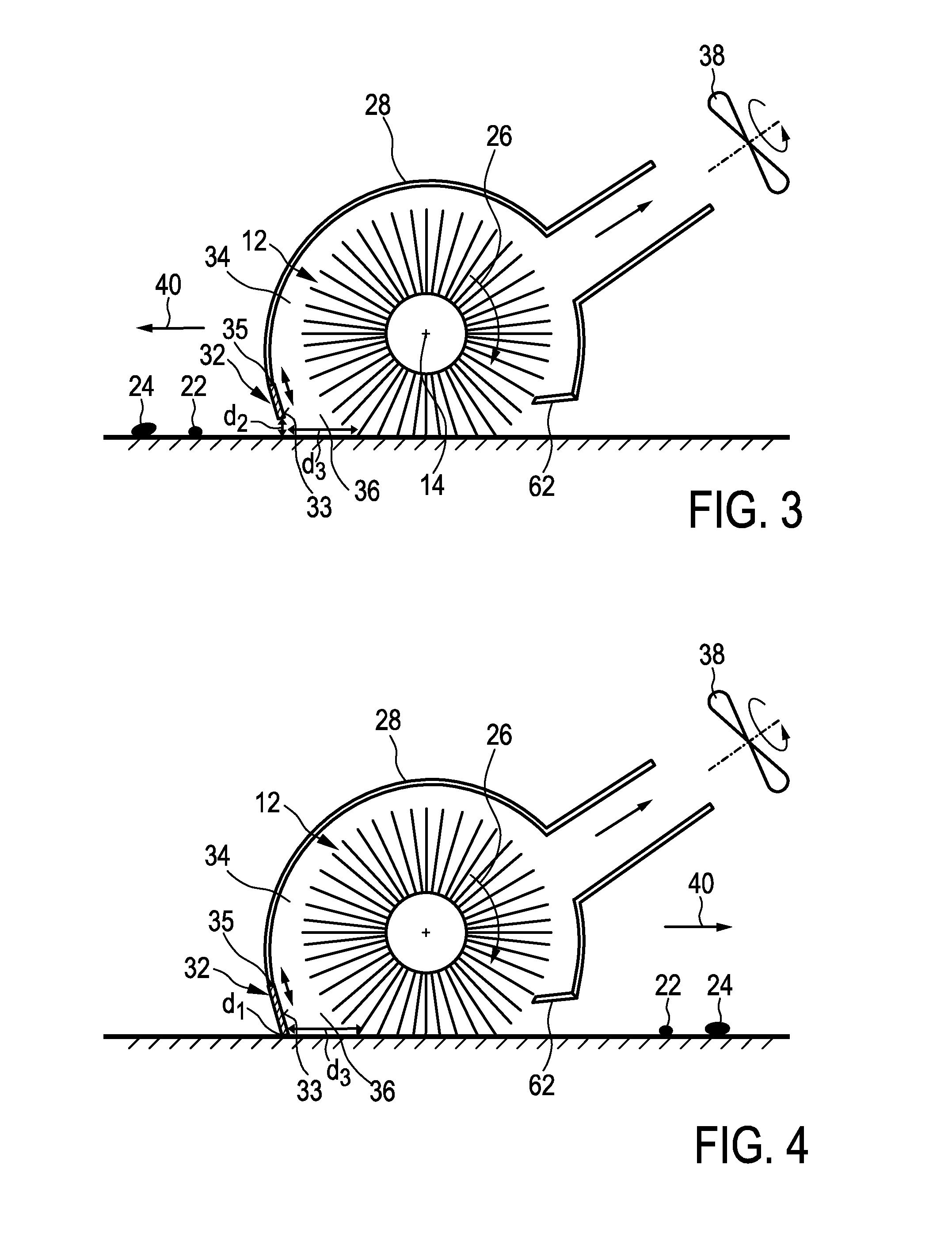
[0107]As shown in FIGS. 3 and 4 illustrating the present invention an additional vacuum aggregate 38 may be provided, which is in these figures only shown in a schematic way. The vacuum aggregate generates an under-pressure in the suction area 34 for ingesting dirt particles 22 and liquid 24 that have been encountered and collected by the brush 12 and the bouncing element 32. It is to be noted that said vacuum aggregate 38 is not necessarily needed. However, an additionally applied under-pressure may further improve the cleaning performance of the device 100. Especially particles 22 that are re-sprayed from the brush 12 to the surface 20 and to not bounce against the bouncing element 33 may in this case also be ingested.

[0108]The under-pressure that is generated by the vacuum aggregate 38 within the suction area 34 preferably ranges between 3 and 70 mbar, more preferably between 4 and 50 mbar, most preferably between 5 and 30 mbar. This under-pressure is, compared to regular vacuum ...


PUM


Abstract

The present invention relates to a cleaning device for cleaning a surface, with a nozzle arrangement (10) comprising: —a brush (12) rotatable about a brush axis (14), said brush (12) being provided with brush elements (16) having tip portions (18) for contacting the surface to be cleaned (20) and picking up dirt particles (22) and/or liquid (24) from the surface (20) during the rotation of the brush (12), —a drive means for driving the brush (12) in rotation, —a bouncing element (32) comprising a bouncing surface (33) that is configured to let the dirt particles (22) and/or liquid (24), that are released from the brush (12) during rotation, rebound to the brush (12), said bouncing surface (33) being spaced apart from the brush (12) and extending substantially parallel to the brush axis (14), and —an adjustment means (35) for adjusting the position of the bouncing element (32) relative to the surface (20) depending on a direction of movement (40) of the device, wherein the adjustment means (35) is adapted to arrange the bouncing element (32) in a first position in which the bouncing element (32) has a first distance d1 to the surface (20), when the cleaning device is moved in a forward direction, in which the bouncing element (32) is, seen in the direction of movement of the device (40), located behind the brush (12), and to arrange the bouncing element (32) in a second position in which the bouncing element (32) has a second distance d2 to the surface, when the cleaning device is moved in an opposite backward direction, wherein d2 is greater than d1 and equal to d3*tan(α), d3 being the distance between the bouncing surface (33) and the position of the brush (12) where the tip portions (18) lose contact from the surface to be cleaned (20) during the rotation of the brush (12), and α being an angle that is equal to or smaller than 20°.

Description

FIELD OF THE INVENTION[0001]The present invention relates to a cleaning device for cleaning a surface. Further, the present invention relates to a nozzle arrangement for such a cleaning device.BACKGROUND OF THE INVENTION[0002]Nowadays electrical floor cleaners can be distinguished into three groups. The first group of floor cleaners uses exclusively an airflow / under-pressure to ingest the dirt directly from the floor, e.g. from the carpet. A second group of floor cleaners makes use of a combination of air flow and a rotating brush. They mostly rely on hard brushes to disperse the dust. Due to the rotation of the brush, the dust will be made airborne from the floor and collected afterwards.[0003]According to the prior art two different concepts are known for collecting the dispersed dust. The first known concept aims at collecting the dust in a so-called dust pan, which is positioned on the floor. Thereto, the dust pan is arranged on the side of the brush where the dust is released f...

Claims


Application Information

Patent Timeline
Patent Type & Authority Applications(United States)
IPC IPC(8): A47L9/04
CPCA47L9/0477A47L9/0488A47L9/066A47L9/0666A47L9/04
Inventor VAN DER KOOI, JOHANNES TSEARDVAN DE VEEN, EGBERT
Owner VERSUNI HLDG BV
Why Eureka
Try Eureka