Cleaning device for cleaning a surface

a cleaning device and surface technology, applied in the direction of vacuum cleaners, carpet cleaners, brushes, etc., can solve the problems of not being solved in a sufficiently satisfactory manner with these devices, the object of vacuuming and mopping the floor with actively sprayed water, and the performance of drying the floor is rather low, so as to improve the cleaning effect and speed up the removal of liquid. , the effect of increasing the capillary force of the brush

Active Publication Date: 2015-10-22
KONINKLJIJKE PHILIPS NV
View PDF2 Cites 33 Cited by
  • Summary
  • Abstract
  • Description
  • Claims
  • Application Information

AI Technical Summary

Benefits of technology

[0068]A factor which may play an additional role in the cleaning function of the rotatable brush is a packing density of the brush elements. When the packing density is large enough, capillary effects may occur between the brush elements, which enhance fast removal of liquid from the surface to be cleaned. According to an embodiment of the present invention the packing density of the brush elements is at least 30 tufts of brush elements per cm2, wherein a number of brush elements per tuft is at least 500.
[0069]Arranging the brush elements in tufts forms additional capillary channels, thereby increasing the capillary forces of the brush for picking-up dirt particles and liquid droplets from the surface to be cleaned.
[0070]As it has been mentioned above, the presented cleaning device has the ability to realize extremely good cleaning results. These cleaning results can be even improved by actively wetting the surface to be cleaned. This is especially advantageous in case of stain removal. The liquid used in the process of enhancing adherence of dirt particles to the brush elements may be provided in various ways. In a first place, the rotatable brush and the flexible brush elements may be wetted by a liquid which is present on the surface to be cleaned. An example of such a liquid is water, or a mixture of water and soap. Alternatively, a liquid may be provided to the flexible brush elements by actively supplying the cleansing liquid to the brush, for example, by oozing the liquid onto the brush, or by injecting the liquid

Problems solved by technology

However, the performance on drying the floor is rather low, since such an agitator is not able to lift liquid from the floor.
The object of vacuuming and mopping the floor with actively sprayed water all in one go is therefore not solved with these devices in a sufficiently satisfactory manner.
It has been identified that such two rotating brushes generate an u

Method used


Image

  • Cleaning device for cleaning a surface
  • Cleaning device for cleaning a surface
  • Cleaning device for cleaning a surface

Examples


first embodiment

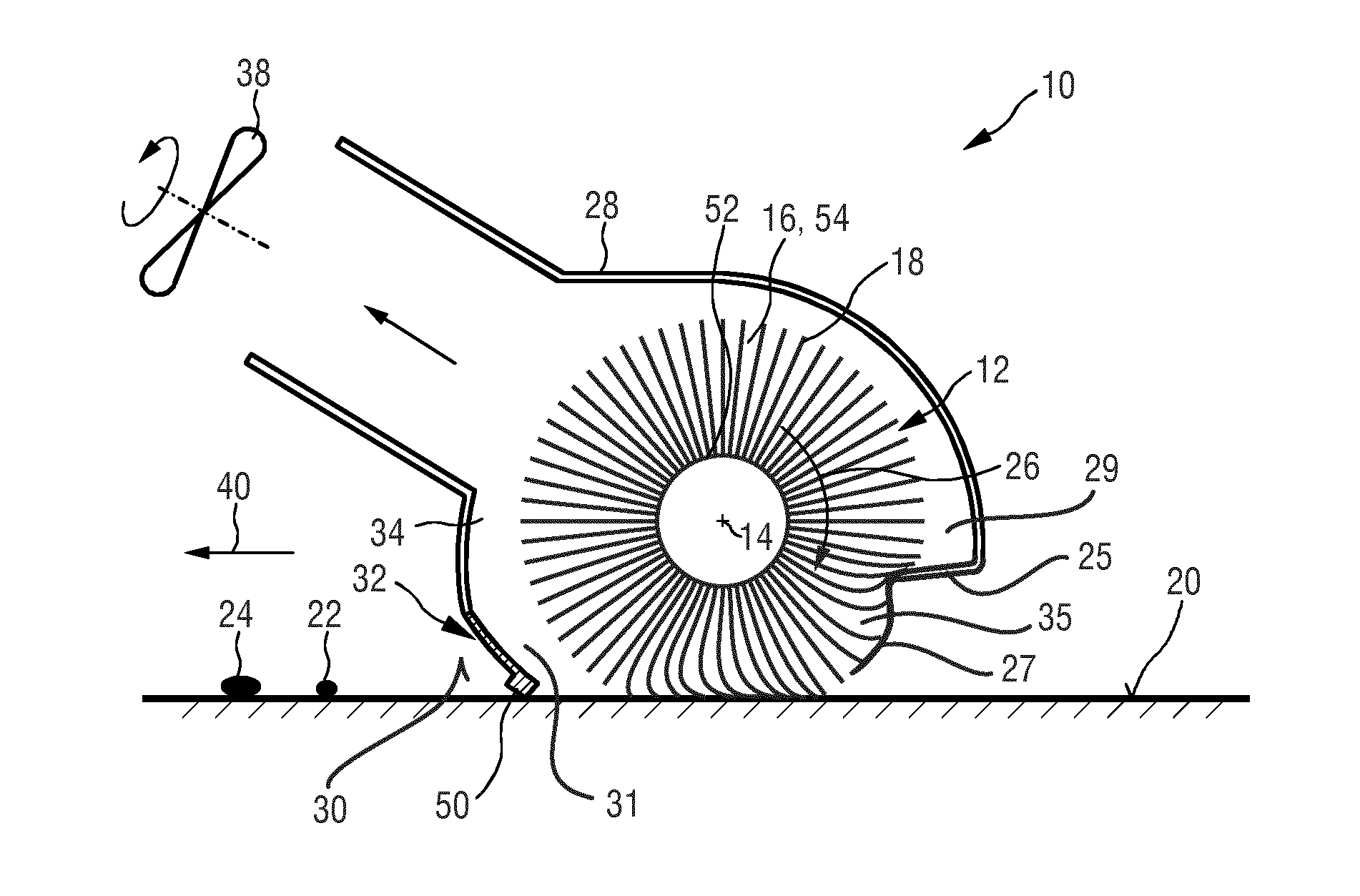
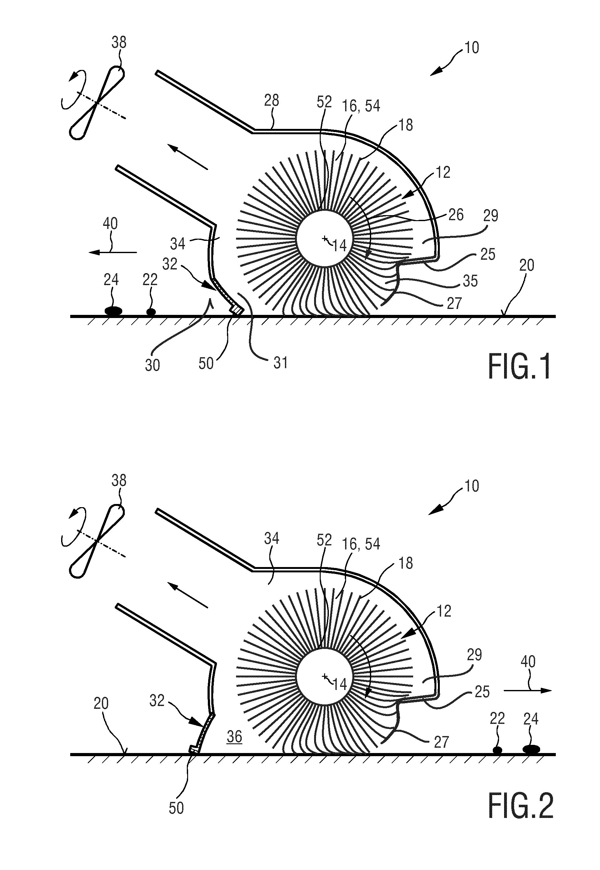
[0086]FIG. 1 shows a schematic cross-section of a nozzle arrangement 10 of a cleaning device 100 according to the present invention. The nozzle arrangement 10 comprises a brush 12 that is rotatable about a brush axis 14. The brush 12 is provided with flexible brush elements 16 which are preferably realized by thin microfiber hairs. The flexible brush elements 16 comprise tip portions 18 which are adapted to contact a surface to be cleaned 20 during the rotation of the brush and to pick-up dirt particles 22 and / or liquid particles 24 from the surface 20 (floor 20) during a pick-up period when the brush elements 16 contact the surface 20.

[0087]Further, the nozzle arrangement 10 comprises a drive unit, e.g. a motor (not shown), for driving the brush 12 in a predetermined direction of rotation 26. The drive unit is preferably adapted to realize a centrifugal acceleration at the tip portions 18 of the brush elements 16 which is, in particular during a dirt release period when the brush e...

second embodiment

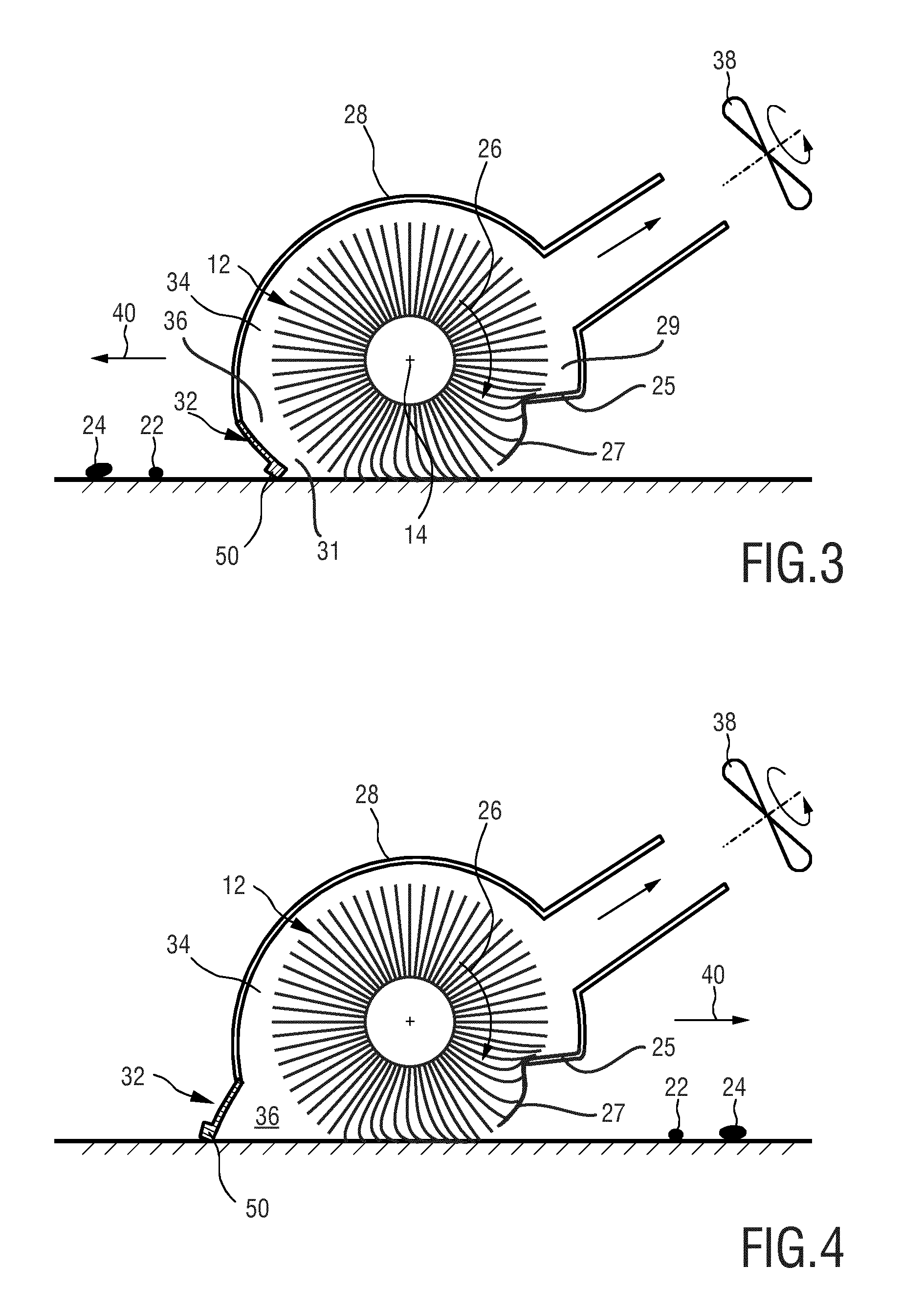
[0110]FIGS. 3 and 4 show the nozzle arrangement 10. These figures illustrate that the positions of the deflector 25 and the restriction element 27 can also be interchanged with a position of the squeegee 32 with respect to the brush 12. However, by comparing FIGS. 3 and 4 with FIGS. 1 and 2 it can be seen that the deflector 25 and the restriction element 27 are still arranged on the second side 29 of the brush 12, where the brush element 16 leave the nozzle housing 28. Similarly is the squeegee 32 still arranged on the first side 31 of the brush 12, where the brush elements 16 enter the nozzle housing 28 during the brush's rotation.

[0111]As it can be seen from FIG. 3, the squeegee 32 has to be in this case in an open position when the nozzle 10 is moved in a forward stroke, in which the nozzle 10 is moved in a direction 40 in which the squeegee 32 is, seen in the direction of movement 40, located in front of the brush 12. Otherwise, the dirt and / or liquid particles 22, 24 would agai...


PUM


Abstract

The present invention relates to a nozzle arrangement (10) for a cleaning device (100) for cleaning a surface, the nozzle arrangement comprising: —a brush (12) rotatable about a brush axis (14), the brush being provided with flexible brush elements (16) having tip portions (18) for contacting the surface to be cleaned (20) and picking up dirt and/or liquid particles (22, 24) from the surface (20) during the rotation of the brush (12), wherein the brush (12) is at least partly surrounded by a nozzle housing (28) and protrudes at least partly from a bottom side (30) of the nozzle housing (28), —a squeegee element (32) which is spaced apart from the brush (12) and attached to the bottom side (30) of the nozzle housing (28) on a first side (31) of the brush (12) where the brush elements (16) enter the nozzle housing (28) during the rotation of the brush (12), wherein the squeegee element (32) is configured for wiping dirt and/or liquid particles (22, 24) across or off the surface to be cleaned (20) during a movement of the cleaning device (100)—a deflector (150) for contacting the brush (12) and deflecting the brush elements (16) during the rotation of the brush (12), and—a restriction element (27) for at least partly restricting air from getting sucked into the nozzle housing (28) at a second side (29) of the brush (12) where the brush elements (16) leave the nozzle housing (28), wherein the restriction element (27) is, seen in a rotation direction (26) of the brush (12), arranged behind the deflector (25), such that the brush elements (16), during the rotation of the brush (12), contact the deflector (25) before passing the restriction element (27) and then leaving the nozzle housing (28) at the bottom side (30), and the restriction element (27) comprises a mechanically flexible element that is, due to its flexibility, configured to follow an outer surface of the brush (12) and to contact the tip portions (18) during the rotation of the brush (12).

Description

FIELD OF THE INVENTION[0001]The present invention relates to a cleaning device for cleaning a surface, and in particular to a nozzle arrangement for such a cleaning device.BACKGROUND OF THE INVENTION[0002]Hard floor cleaning these days is done by first vacuuming the floor, followed by mopping it. Vacuuming removes the coarse dirt, while mopping removes the stains. From the state of the art many appliances, especially targeting the professional cleaning sector, are known that claim to vacuum and mop in one go. Appliances for the professional cleaning sector are usually specialized for big areas and perfectly flat floors. They rely on hard brushes and suction power to get water and dirt from the floor. Appliances for home use often use a combination of a hard brush and a double-squeegee nozzle. Like the appliances for the professional sector these products use the brush to remove stains and the squeegees in combination with an under-pressure to lift the dirt from the floor.[0003]The s...

Claims


Application Information

Patent Timeline
IPC IPC(8): A47L7/00A47L9/04A47L11/40A47L11/282A47L11/292
CPCA47L7/0009A47L7/0042A47L11/282A47L11/292A47L9/0488A47L11/4044A47L11/4077A47L9/0411A47L9/0477A47L11/4041A46B13/001
Inventor VAN DER KOOI, JOHANNES TSEARDROUMEN, BRITTLUBBERS, MATTHIJS HENDRIKUS
Owner KONINKLJIJKE PHILIPS NV
Why Eureka
Try Eureka