Robot system having robot operated in synchronization with bending machine

Inactive Publication Date: 2016-09-08
FANUC CORP
View PDF1 Cites 7 Cited by
  • Summary
  • Abstract
  • Description
  • Claims
  • Application Information

AI Technical Summary

Benefits of technology

[0009]An object of the present invention is to provide a robot system for carrying out a bending process with respect

Problems solved by technology

Since the workpiece is bent so as to trace an arc by being supported by a processing knife as a fulcrum, it is necessary to teach at least three points in a motion program of a robot for gripping the workpiece, i.e., a start point, an end point and an intermediate point

Method used


Image

  • Robot system having robot operated in synchronization with bending machine
  • Robot system having robot operated in synchronization with bending machine
  • Robot system having robot operated in synchronization with bending machine

Examples


first working example

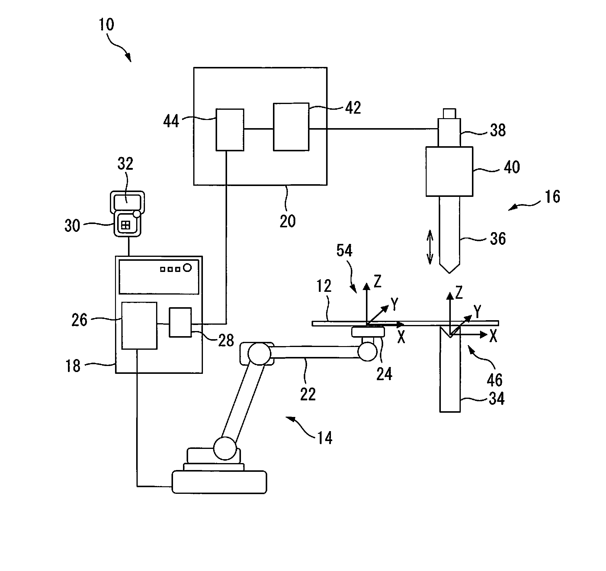
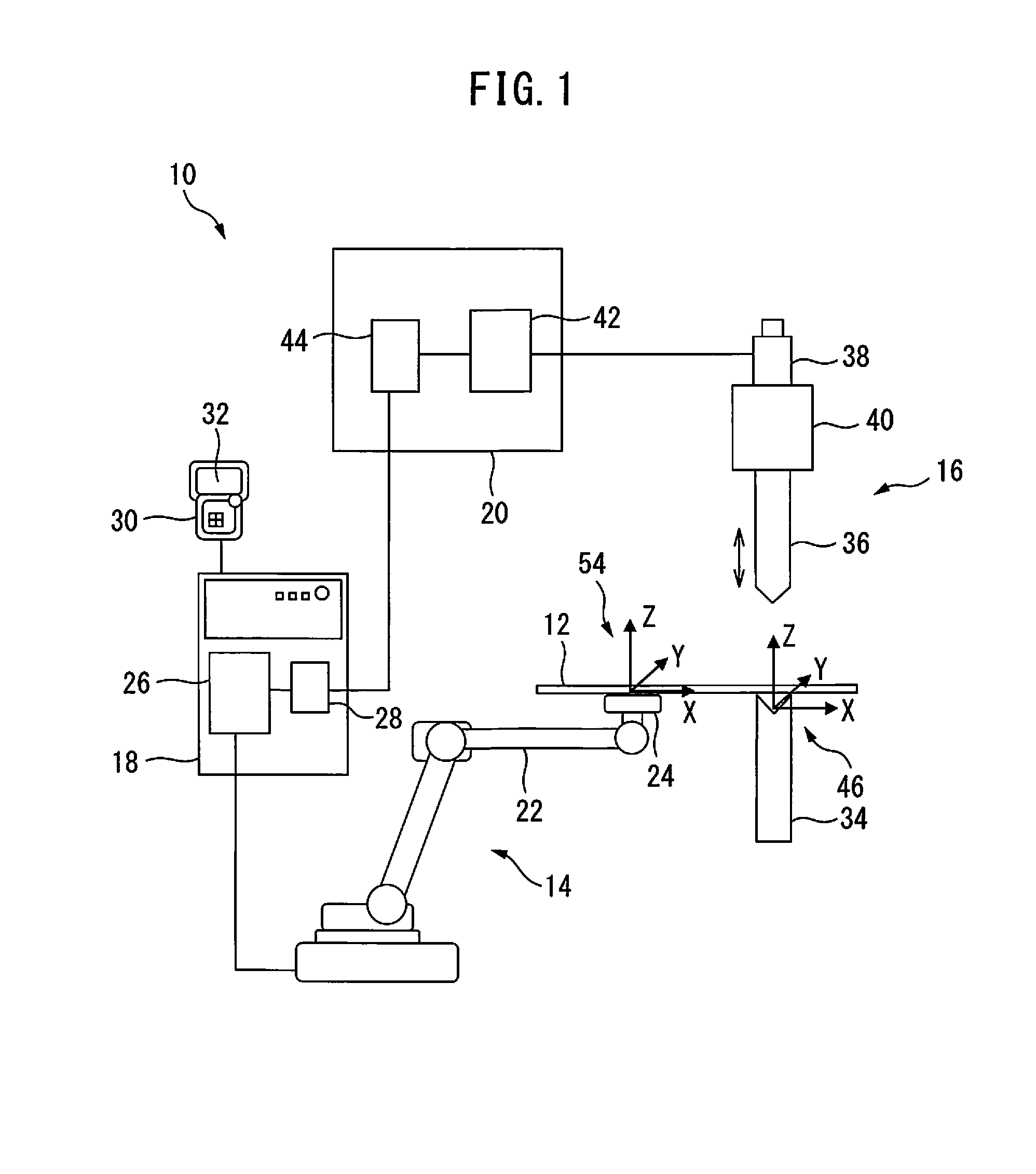
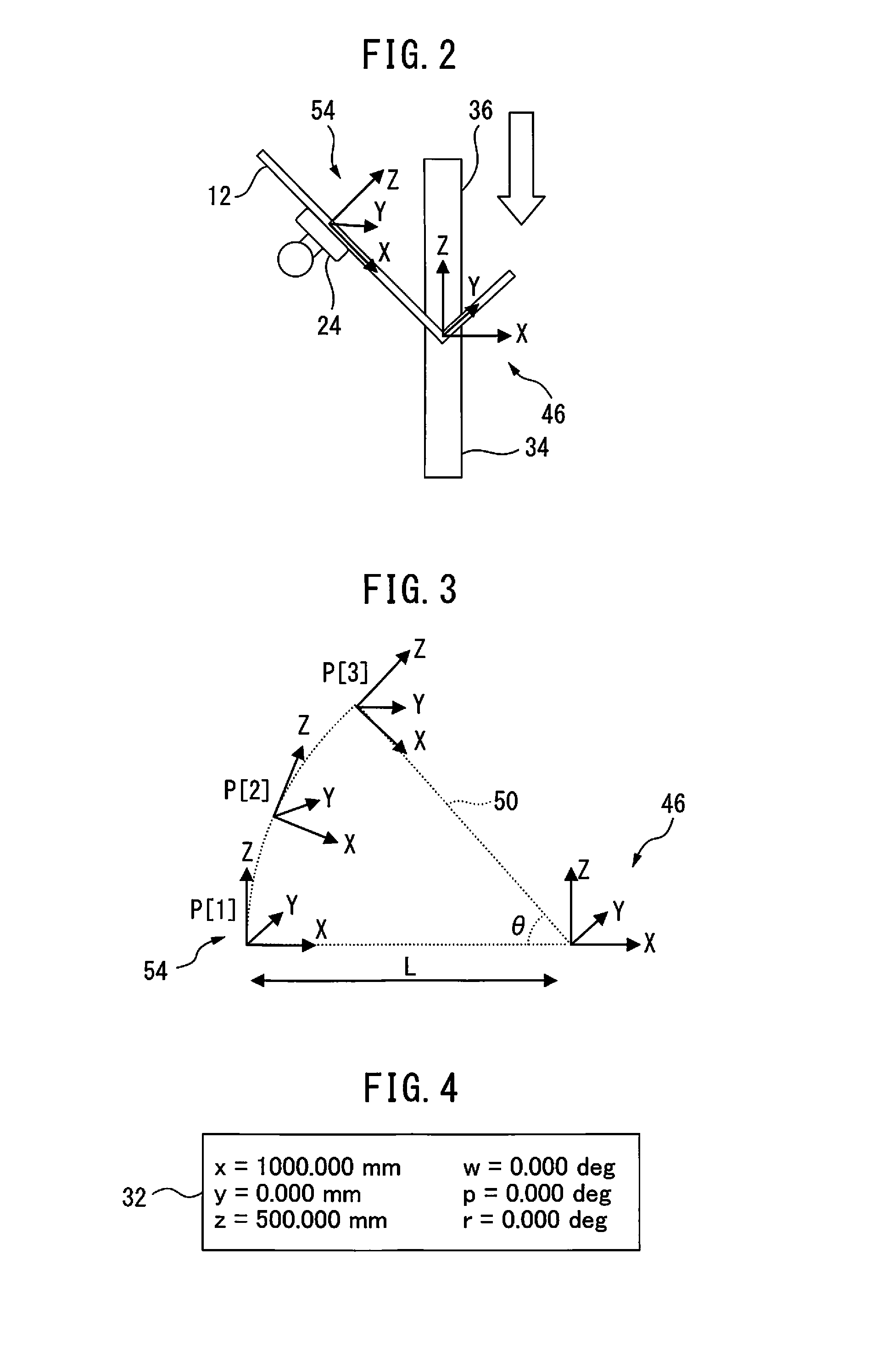
[0041]First, as shown in FIG. 1 or 3, a user coordinate system 46 is set or determined so as to specify a rotation axis (or a center line of rotation) of the bending motion in the bending process. For example, user coordinate system 46 may be set by inputting the position and / or angle of each axis of robot 14 to teaching pendant 30 by the operator, as exemplified in FIG. 4 (screen 32 of teaching pendant 30). In addition, in the example of FIG. 1, user coordinate system 46 is set so that the Y-axis thereof coincides with an edge of die 34 (in FIG. 1, the Y-axis extends perpendicular to the drawing sheet).

[0042]Next, as shown in FIG. 5, in a teaching program 48 of robot 14, a process start position P[1] and an operation form are defined so as to add a bending process command (BEND_START), and a rotation angle (θ) of the bending process (bending motion) and an angular velocity of a command line 50 about the rotation axis (in this case, 90 deg / sec) are designated. By virtue of this, an ...

second working example

[0047]First, as shown in FIG. 1 or 7, user coordinate system 46 is set or determined so as to specify the rotation axis (or the center line of rotation) of the bending motion in the bending process. For example, similarly to the first working example, user coordinate system 46 may be set by inputting the position and / or angle of each axis of robot 14 to teaching pendant 30 by the operator, as exemplified in FIG. 4 (screen 32 of teaching pendant 30). In addition, in the example of FIG. 1, user coordinate system 46 is set so that the Y-axis thereof coincides with the edge of die 34 (in FIG. 1, the Y-axis extends perpendicular to the drawing sheet).

[0048]Next, as shown in FIG. 8, in a teaching program 56 of robot 14, by designating a rotation angle (θ) of the bending process (bending motion), an angular velocity of command line 50 about the rotation axis (in this case, 90 deg / sec), a radius (L) of the bending motion in the X-direction of user coordinate system 46, and a rotation angle ...

third working example

[0053]First, as shown in FIG. 8, in teaching program 56 of robot 14, a rotation angle (θ) of the bending process (bending motion), an angular velocity of command line 50 about the rotation axis (in this case, 90 deg / sec), a radius (L) of the bending motion in the X-direction of user coordinate system 46, and a rotation angle (φ) about the Z-axis of user coordinate system 46 are designated. In this regard, similarly to the first working example, process start position P[1] refers to a portion of workpiece 12 held by robot 14. For example, by carrying out a touch-up operation with respect to die 34 during robot 14 holds workpiece 12, process start position P[1] can be taught in robot teaching program 48.

[0054]Due to the above procedure, user coordinate system 46 is set or determined so as to specify the rotation axis (or the center line of rotation) in the bending process, as shown in FIG. 7. Further, a process start position P[1] and an operation form are defined so as to add a bendi...


PUM

PropertyMeasurementUnit
Angleaaaaaaaaaa
Distanceaaaaaaaaaa
Angular velocityaaaaaaaaaa

Abstract

A robot system for carrying out a bending process with respect to a workpiece held by a robot, in which an arc interpolation motion of the robot can be easily and precisely taught. A user coordinate system is set so as to specify a rotation axis of the bending motion in the bending process by inputting the position and/or angle of each axis of the robot to a teaching pendant by the operator. Next, in a teaching program of the robot, a process start position and an operation form are defined so as to add a bending process command, and a rotation angle of the bending process and an angular velocity of a command line about the rotation axis are designated. By virtue of this, an internal program for carrying out an arc interpolation motion by the robot is generated in a robot controlling part.

Description

BACKGROUND OF THE INVENTION[0001]1. Field of the Invention[0002]The present invention relates to a robot system for gripping a workpiece by using a robot and carrying out a bending process, while operating the robot in synchronization with a bending machine.[0003]2. Description of the Related Art[0004]Generally, in a bending machine such as a press brake, etc., the position and orientation (hereinafter, also referred to as position / orientation) of a workpiece are detected by a sensor, and a robot hand is moved to the detected position / orientation so as to grip and take out the workpiece. As a relevant prior art document, JP H06-015370 A discloses a method and a device, in which a trajectory for circular interpolation of the motion by a bending robot arranged on a bender is calculated so as to follow up the bending motion during a workpiece is gripped by a gripper of the robot, a thrust amount of a cutting edge of the bender corresponding to a bending angle by the circular interpolat...

Claims


Application Information

Patent Timeline
IPC IPC(8): B25J9/16B21D5/00B25J9/00
CPCB25J9/1664B21D5/006B25J9/0096B21D5/01B21D7/06B25J11/005B21D5/02B21D5/0281G05B2219/39105Y02P90/02
Inventor TAKAYAMA, YUUSUKE
Owner FANUC CORP
Why Eureka
Try Eureka