Image forming apparatus and developing gap adjusting method in image forming apparatus

Active Publication Date: 2006-06-01
KK TOSHIBA +1
View PDF2 Cites 3 Cited by
  • Summary
  • Abstract
  • Description
  • Claims
  • Application Information

AI Technical Summary

Benefits of technology

[0009] It is an object of this invention to provide an image forming apparatus and a developing gap adjusting method thereof to obtain highly precise and reproducible high grade, highly precise and reproducible images by adjusting a gap between the developing rollers of a revolving type developing device and a photosensitive drum easily and precisely.
[0010] According to the embodiment of the present invention, there is provided an image forming apparatus comprising: an image carrier; a developing unit equipped with a developing roller to supply developer to the image carrier; a rotatable supporting member positioned for the image carrier to support the developing unit; a guide provided in a periphery of the supporting member and capable of sliding the developing roller at the position opposite to the image carrier in parallel with a line connecting the rotating center of the image carrier and the rotating center of the supporting member; and an adjusting member to move the developing roller in the guide, set the position of the developing roller in the guide and finely adjust a gap between the image carrier and the developing roller.

Problems solved by technology

That is, whenever the developing roller adjusting holder is adjusted, the developing position on the photosensitive drum is shifted the optimum development by the developing roller cannot be obtained and the highly precise development of images is impeded.

Method used


Image

  • Image forming apparatus and developing gap adjusting method in image forming apparatus
  • Image forming apparatus and developing gap adjusting method in image forming apparatus
  • Image forming apparatus and developing gap adjusting method in image forming apparatus

Examples


Embodiment Construction

[0027] The embodiment of this invention will be described below in detail referring to the attached drawings.

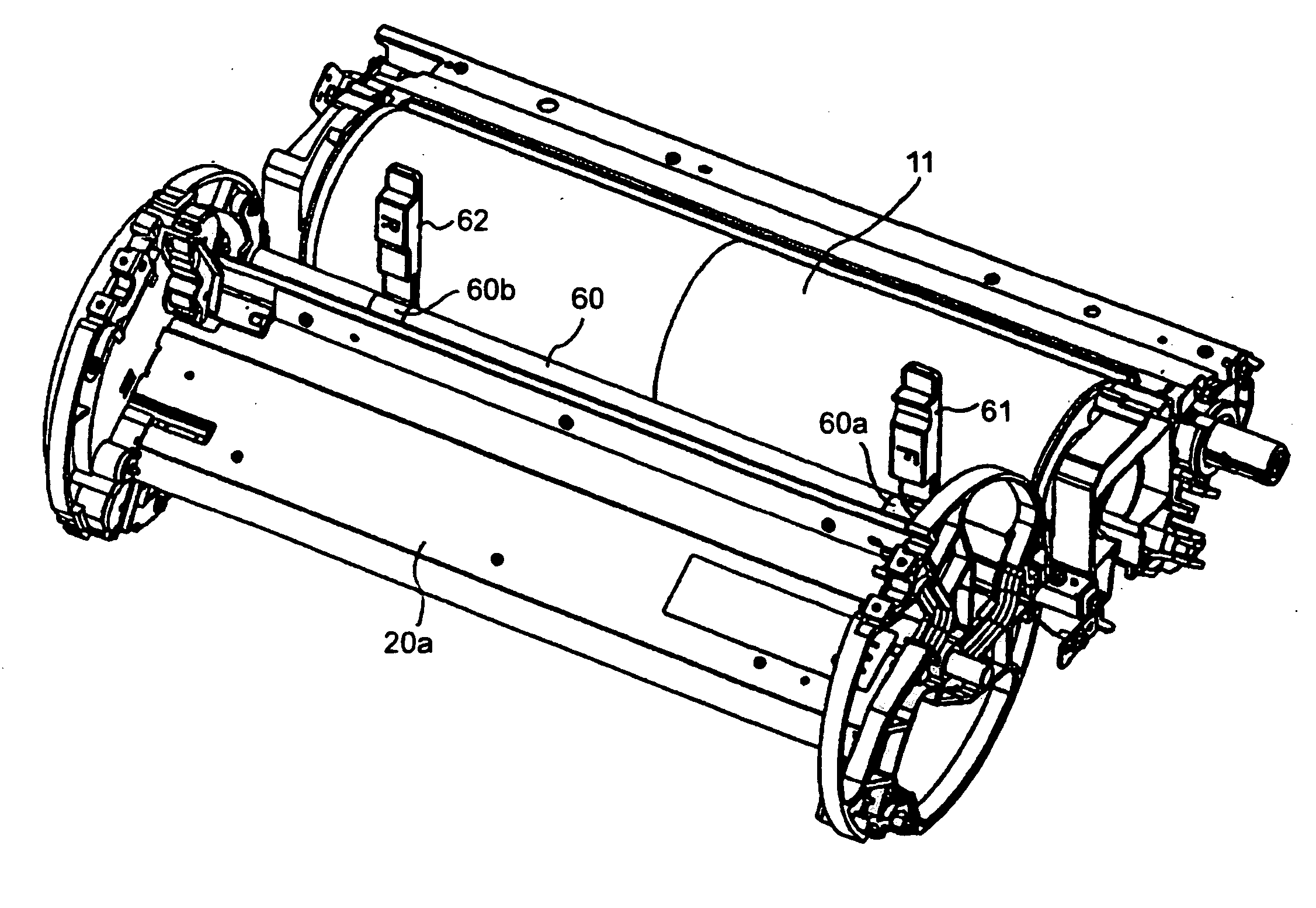
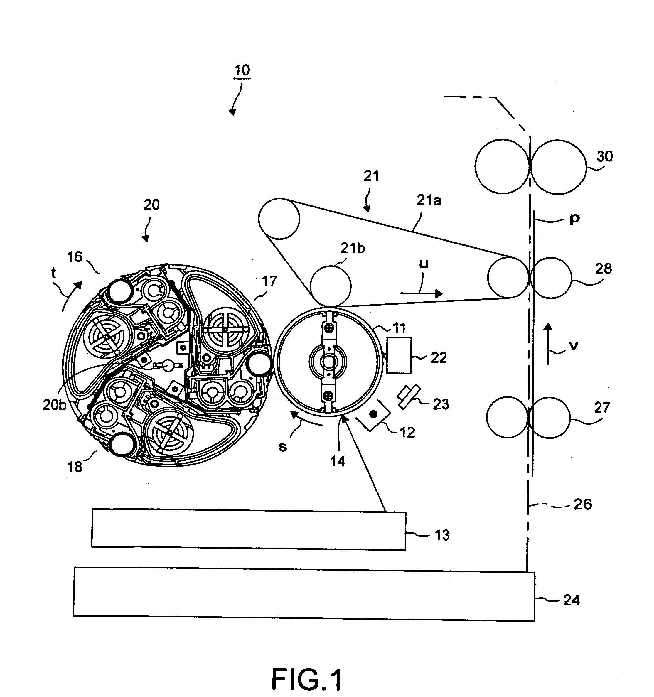
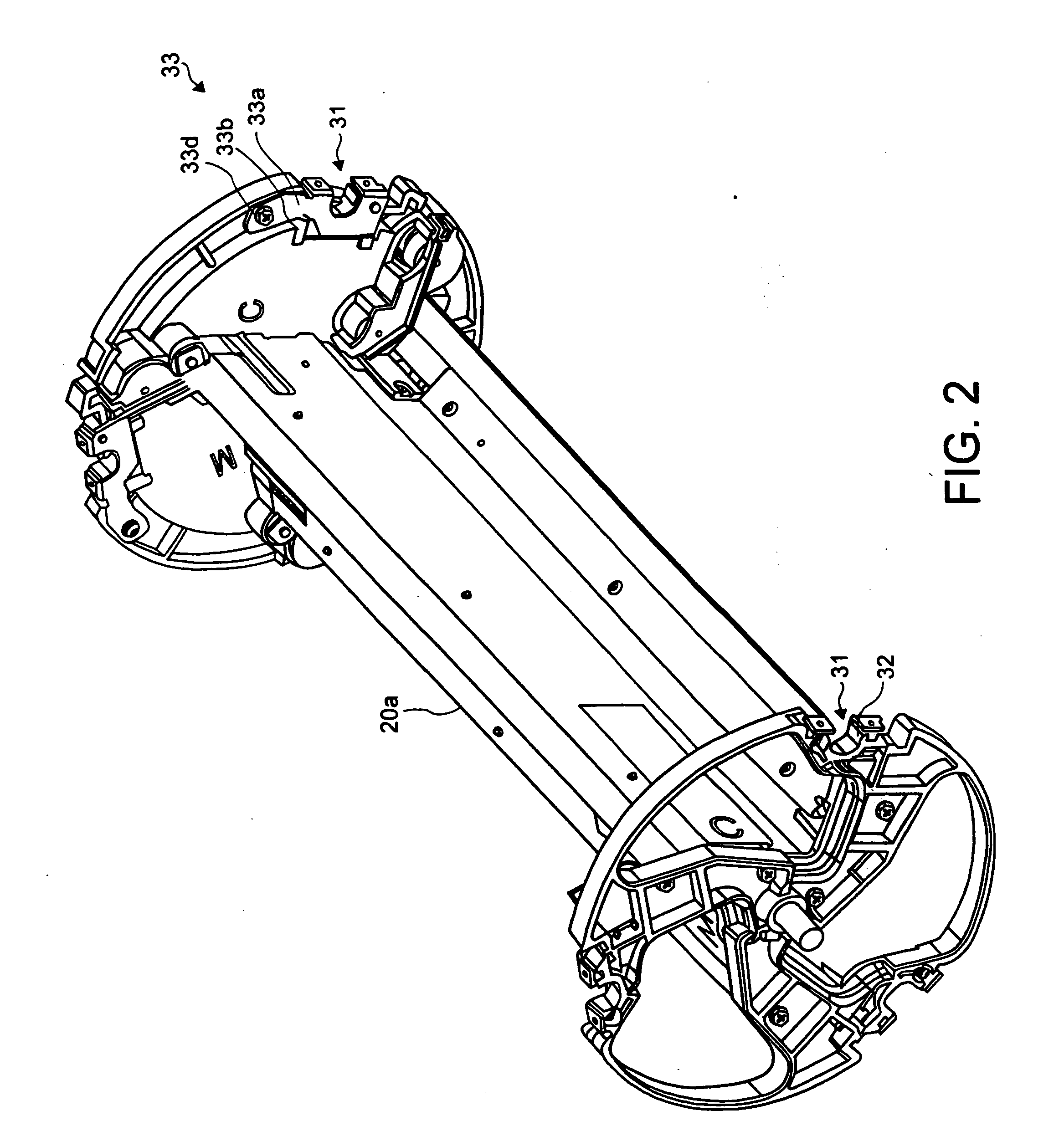
[0028]FIG. 1 is a schematic construction diagram showing an image forming unit 10 of such an image forming apparatus as a color printer, etc. in the embodiment of this invention. Around photosensitive drum 11, which is an image carrier, of image forming unit 10, a main charger 12 to uniformly charge photosensitive drum 11 following its rotation in the arrow direction s and an irradiation position 14 of a laser beam 13a from a laser writing unit 13 for forming a latent image on charged photosensitive drum 11 are arranged. Further, around photosensitive drum 11, there are a revolver type color developing device 20 to support developing units 16, 17, 18 rotatably in the arrow direction t by the rotating holder 20a for developing a latent image on photosensitive drum 11 with yellow (Y), magenta (M) and cyan (C) developers, a middle transfer unit 21 having a middle transfer belt ...


PUM


Abstract

In the image forming apparatus of the present invention, a developing roller is press fit into the rotor at the edge of the rotary holder of the revolver type color developing device that is positioned against the photosensitive drum and a developing gap between the photosensitive drum and the developing roller is finely adjusted in parallel to a line connecting the center of the photosensitive drum and the rotary holder by sliding the developing roller in the rotor by the adjuster. Irrespective of the adjustment of the developing gap, the developing position on the photosensitive drum is always kept at a constant position and a developing image of high level of quality is obtained.

Description

BACKGROUND OF THE INVENTION [0001] 1. Field of the Invention [0002] The present invention is concerned with such image forming apparatus as electro-photographic apparatus, printers, etc. and relates to an image forming apparatus to obtain color developing images using a revolver type color developing device. [0003] 2. Description of the Related Art [0004] For a multi-color image forming apparatus having the plural number of developing units in order to obtain color images according to electro-photographing system of color copiers, color printers, etc., the downsizing is so far demanded. In response to this demand, a revolver type color developing device is developed in recent years. [0005] In this revolver type color developing device, 3 developing units to supply yellow (Y), magenta (M) and cyan (C) toners, respectively are installed in a single rotating holder and the rotary holder further equipped with a black (BK) toner additionally is rotated to arrange the developing units in ...

Claims


Application Information

Patent Timeline
IPC IPC(8): G03G15/01
CPCG03G15/0813G03G2215/0634G03G2221/163
Inventor TANAKA, YOSHIAKI
Owner KK TOSHIBA
Why Eureka
Try Eureka