Cable tie with support member

Inactive Publication Date: 2016-09-08
AVERY DENNISON CORP
4 Cites 2 Cited by

AI-Extracted Technical Summary

Problems solved by technology

Due to its paper-based construction, this type of packaging is not particularly rigid or durable in nature.
Rather, it has been found that paper-based packaging is often torn or otherwise deformed prior to purchase, either in an intentional or unintentional manner.
As a result, it has been found that the retentive force applied by the cable tie can cause either the strap to tear or deform the packaging about the periphery of each slot and/or the head to penetrate partially or entirely through the portion of the packagin...

Benefits of technology

[0012]It is an object of the present invention to provide a new and improved cable t...

Abstract

A unitary, plastic cable tie for use in securing an article to packaging includes an elongated, serrated strap and a support member that extend orthogonally out from opposing surfaces of an apertured head. The support member includes an enlarged, planar backing plate pivotally connected to the head through a flexible, tabular neck. In use, the cable tie is folded through the neck such that the backing plate overlies the rear wall of the head. The strap is then inserted through both a fitted slot in the backing plate and a first opening in the packaging, wrapped transversely across the article, disposed through both an enlarged opening in the backing plate and a second opening in the packaging, and into engagement with the head. In this manner, the retentive force applied by the cable tie onto the packaging is dispersed evenly across the relatively large surface area of the backing plate.

Application Domain

Flexible elementsHaberdashery

Technology Topic

BackplaneMechanical engineering

Image

  • Cable tie with support member
  • Cable tie with support member
  • Cable tie with support member

Examples

  • Experimental program(1)

Example

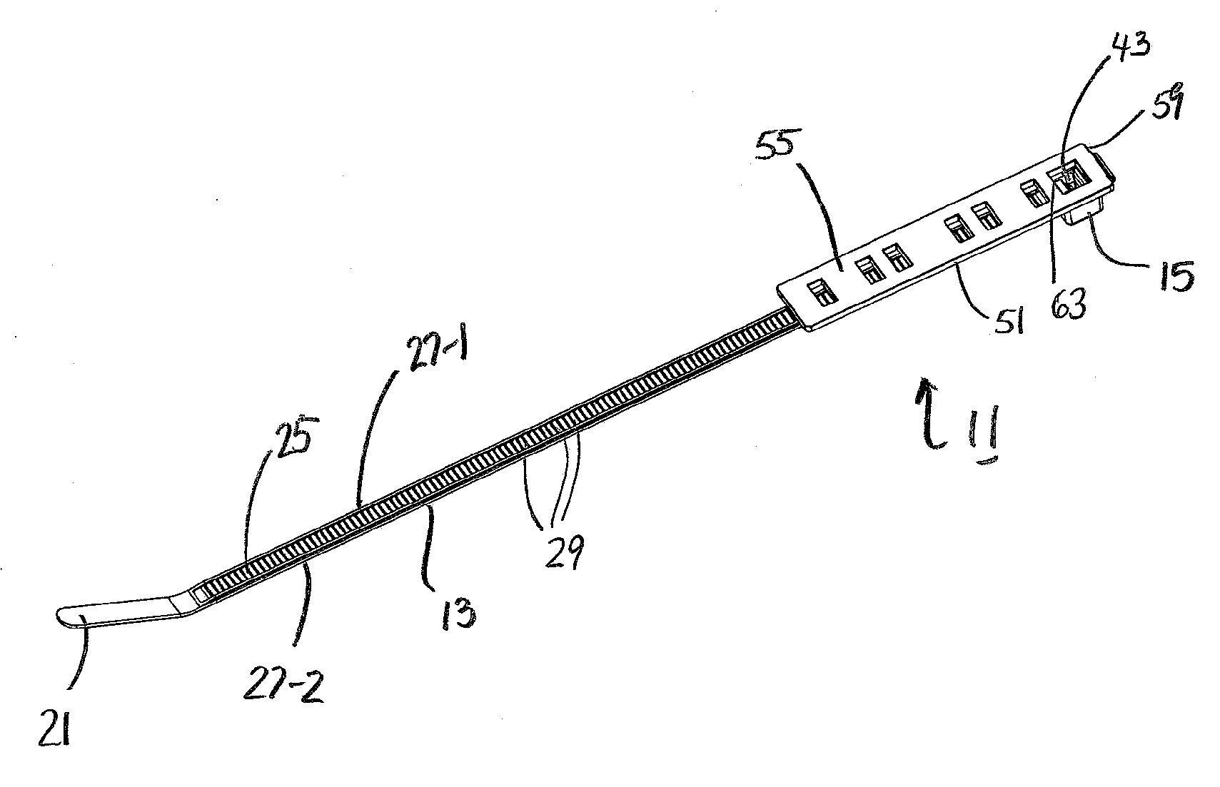
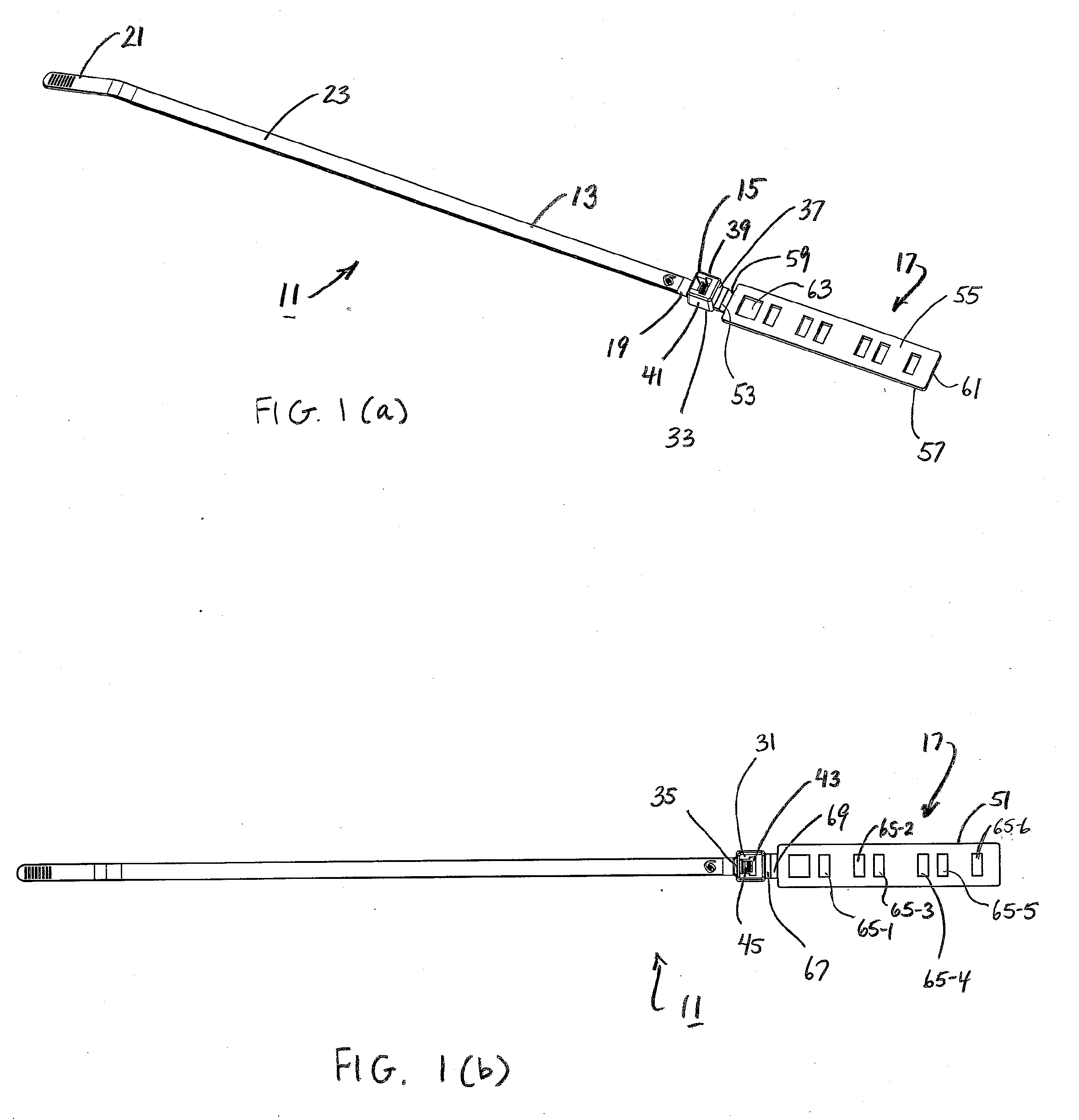
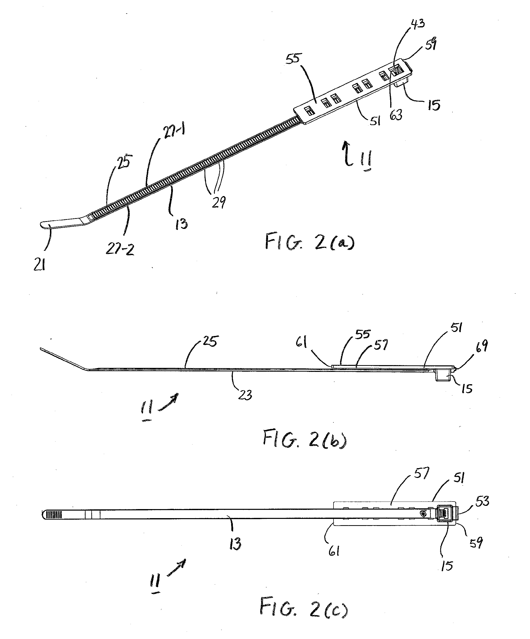
[0022]Referring now to FIGS. 1(a)-2(c), there is shown a cable tie constructed according to the teachings of the present invention, the cable tie being identified generally by reference numeral 11. In use, cable tie 11 can be formed in a closed loop configuration in order to, inter alia, secure an article of commerce to its corresponding packaging. As will be explained further in detail below, cable tie 11 is specifically designed to disperse the retentive force applied to the packaging across a broader region of contact, thereby enabling the packaging to absorb the retentive forces without tearing, which is a principal object of the present invention.
[0023]Cable tie 11 is a unitary member that comprises an elongated strap 13, a locking head 15 formed onto one end of elongated strap 13, and a support member 17 formed onto locking head 15. As will be described in detail below, support member 17 provides structural reinforcement to the packaging to which cable tie 11 is secured and thereby serves as a principal feature of the present invention.
[0024]Preferably, cable tie 11 is constructed from a durable and inexpensive plastic material (e.g. nylon, polyethylene, polypropylene, acetal, polyamide or a composite thereof) using conventional molding techniques. However, it is to be understood that cable tie 11 could be manufactured using a wide variety of alternative materials without departing from the spirit of the present invention.
[0025]Strap 13 is constructed as an elongated flexible band that has a generally uniform rectangular shape in lateral cross-section along the majority of its length. However, it is to be understood that strap 13 could be constructed in alternative shapes and configurations without departing from the spirit of the present invention.
[0026]Strap 13 comprises a first end 19, a second end 21, a substantially flat front surface 23, a bottom surface 25 and a pair of opposing, longitudinally extending side members, or rails, 27-1 and 27-2. As seen most clearly in FIG. 2(a), a plurality of ratchet-shaped teeth 29 are integrally formed into bottom surface 25 along the majority of its length, each tooth 29 extending laterally across bottom surface 25 between side members 27-1 and 27-2. As will be explained further below, teeth 29 are designed to be sequentially engaged by locking head 15 when cable tie 11 is formed into a closed loop configuration.
[0027]As seen most clearly in FIGS. 1(a) and 1(b), locking head 15 is constructed as an enlarged, rectangular block, or buckle, that is shaped to include a front wall 31, a rear wall 33, an inner end wall 35, an outer end wall 37, a left sidewall 39, and a right sidewall 41 that together define an elongated strap accepting channel 43 that extends through head 15 from front wall 31 to rear wall 33.
[0028]As can be seen, first end 19 of strap 13 is integrally formed onto the outer surface of inner end wall 35 and extends generally orthogonally out therefrom. Furthermore, elongated channel 43 is generally rectangular in transverse cross-section and is appropriately dimensioned to fittingly receive a section of strap 13 when tie 11 is formed into a closed loop.
[0029]Locking head 15 additionally comprises a deflectable pawl, or locking tang, 45 that is pivotally coupled to the inner surface of inner end wall 35 along rear wall 33. Pawl 45 is naturally oriented to project into elongated channel 43 and selectively engage strap 13 when inserted into locking head 15, as will be explained further below.
[0030]Pawl 45 is preferably constructed as generally a block-shaped member that includes a plurality of ratchet-shaped teeth at its distal end. In this manner, it is intended that multiple teeth on pawl 45 engage corresponding teeth 29 on strap 13 to maximize the strength of engagement between locking head 15 and strap 13 when cable tie 11 is formed into a closed loop configuration. However, it is to be understood that alternative styles of pawls, such as relatively flat, planar members, could be utilized in place of pawl 45 without departing from the spirit of the present invention.
[0031]Referring now to FIGS. 1(a), 1(b) and 2(c), support member 17 includes a backing plate 51 that is pivotally connected to the outer surface of outer end wall 37 by a flexible neck 53. As will be explained further below, backing plate 51 can be used to provide support to packaging to which cable tie 11 is secured, thereby reducing the risk of any damage to the packaging.
[0032]Backing plate, or pad, 51 is constructed as an enlarged, rectangular, planar platform that includes a flattened front surface 55, a flattened rear surface 57, an inner edge 59 and an outer edge 61. As can be seen, backing plate 51 has a width that is slightly greater than the width of locking head 15 and a length that is considerably longer than the length of locking head 15. The enlarged overall footprint of backing plate 51 creates a relatively broad, or disperse, region of contact against the packaging to which cable tie 11 is secured, which is highly desirable for reasons to be explained further below.
[0033]It should be noted that backing plate 51 is not limited to a rectangular shape. Rather, it is to be understood that backing plate 51 could be formed into alternative configurations (e.g. as a square-shaped or disc-shaped member with an enlarged, planar, front surface) without departing from the spirit of the present invention.
[0034]Backing plate 51 is shaped to define an enlarged transverse hole, or opening, 63 in close proximity to inner edge 59. Opening 63 is positioned to directly align with strap accepting channel 43 when backing plate 51 is pivoted rearward about neck 53 and into contact against bottom surface 25 of strap 13 and rear wall 33 of locking head 15, as shown in FIG. 2(a). Preferably, opening 63 has the same general dimensions in transverse cross-section as strap accepting channel 43 at rear wall 33 so that backing plate51 does not interfere with the insertion of strap 13 through apertured locking head 15.
[0035]Backing plate 51 is additionally shaped to define a plurality of transverse slots 65-1 thru 65-6 that are formed in parallel in plate 51 at various locations along its length. Each slot 65 preferably has the same general dimensions in transverse cross-section as strap 13. As such, strap 13 is appropriately dimensioned to be fittingly inserted through one of slots 65 when tie 11 is formed into its closed loop configuration, as will be explained further below.
[0036]As seen most clearly in FIGS. 1(a) and 1(b), neck 53 is a shortened tabular member that connects outer end wall 37 of locking head 15 to inner edge 59 of backing plate 51, the width of neck 53 being approximately equal to the width of strap 13. Neck 53 includes a stiffened, or rigid, inner portion 67 that forms the connection with outer end wall 37 and a flexible outer portion 69 that forms the connection with backing plate 51.
[0037]Inner portion 67 preferably has the same approximate thickness and rigidity as strap 13. By contrast, outer portion 69 preferably has a thickness that is considerably less than the thickness of strap 13. As a result, cable tie 11 is designed to flex through reduced thickness portion 69. In this manner, neck 53 functions as a living hinge through which backing plate 51 can pivot relative to locking head 15.
[0038]Cable tie 11 is initially constructed such that backing plate 51 extends orthogonally out from outer end wall 37 and lies in a generally coplanar relationship with strap 13, as shown in FIGS. 1(a) and 1(b). In other words, front surface 55 of backing plate 51 lies in the same plane defined by front surface 23 of strap 13 and rear surface 57 of backing plate 51 lies in the same plane defined by bottom surface 25 of strap 13.
[0039]At the same time, the hinged construction of neck 53 enables backing plate 51 to be pivoted rearward until rear surface 57 of backing plate 51 contacts both rear wall 33 of locking head 15 and a section of bottom surface 25 of strap 13, as shown in FIGS. 2(a)-(c). Disposed in this folded condition, cable tie 11 is able to secure an article of commerce to its corresponding packaging without imparting any damage to the packaging, which is a principal object of the present invention.
[0040]In use, tie 11 can be used in the following manner to secure an article of commerce to its corresponding packaging. As referenced above, cable tie 11 is initially constructed such that backing plate 51 extends orthogonally out from outer end wall 37 so as to lie in a generally coplanar relationship with strap 13, as shown in FIGS. 1(a) and 1(b). Once desired for use, backing plate 51 is pivoted rearward such that rear surface 57 of backing plate 51 is drawn towards rear wall 33 of locking head 15 and bottom surface 25 of strap 13, as shown in FIGS. 2(a)-(c).
[0041]With the article of commerce disposed in position against the front surface of its corresponding packaging, exposed front surface 55 of backing plate 51 is disposed against the rear surface of the packaging. More specifically, backing plate 51 is preferably disposed against the rear surface of the packaging such that inner edge 59 and outer edge 61 are aligned on opposite sides of the article to be coupled.
[0042]Free end 21 of strap 13 is then inserted through a slot 65 in backing plate 51 (i.e. in the direction from rear surface 57 to front surface 55), as shown in FIGS. 3(a)-(c). With strap 13 pulled taut through slot 65, rear surface 57 of backing plate 51 abuts firmly against rear wall 33 of locking head 15 as well as against a section of bottom surface 25 of strap 13.
[0043]Free end 21 of strap 13 is then passed forward through the packaging on one side of the article. Preferably, a first narrow opening is formed in the packaging to facilitate insertion of strap 13 therethrough. Strap 13 is then wrapped transversely across the article and inserted rearward through a second narrow opening formed in the packaging.
[0044]Preferably, strap 13 is initially positioned such that opening 63 in backing plate 51 directly aligns with the second narrow opening formed in the packaging, thereby facilitating insertion of second end 21 of strap 13 through strap accepting channel 43. Additionally, strap 13 is preferably inserted through the particular slot 65 in backing plate 51 that is in closest alignment with the first narrow opening in the packaging. In this manner, it is to be understood that the inclusion of a plurality of parallel slots 65 in backing plate 51 enables strap 13 to wrap tightly around articles of varying widths. In this manner, it is envisioned that cable tie 11 could be utilized in a wide variety of potential applications.
[0045]Cable tie 11 is formed into a closed loop by inserting free end 21 of strap 13 through strap accepting channel 43 in in locking head 15, as seen in FIGS. 3(a)-(c). With cable tie 11 formed into a closed loop, free end 21 of serrated strap 13 is advanced through locking head 15 until strap 13 cinches tightly across the article, with pawl 45 lockably engaging ratchet-shaped teeth 29 to prevent withdrawal, or backing out, of strap 13 from locking head 15. As such, the engagement of pawl 45 onto strap 13 secures cinched cable tie 11 in its closed loop configuration and thereby retains the article firmly against the front surface of the packaging.
[0046]With tie 11 configured in the manner set forth in detail above, the entire front surface 55 of backing member 51 is disposed in contact against the packaging. As a result, the relatively large surface area of front surface 55 disperses the region of contact between cable tie 11 and the packaging. By significantly expanding this region of contact, the retentive force applied by cable tie 11 onto the packaging is less concentrated, thereby reducing the likelihood of damage to packaging as compared with conventional cable ties (i.e. cable ties that do not include a support member).
[0047]The embodiment shown above is intended to be merely exemplary and those skilled in the art shall be able to make numerous variations and modifications to it without departing from the spirit of the present invention. All such variations and modifications are intended to be within the scope of the present invention as defined in the appended claims.

PUM

no PUM

Description & Claims & Application Information

We can also present the details of the Description, Claims and Application information to help users get a comprehensive understanding of the technical details of the patent, such as background art, summary of invention, brief description of drawings, description of embodiments, and other original content. On the other hand, users can also determine the specific scope of protection of the technology through the list of claims; as well as understand the changes in the life cycle of the technology with the presentation of the patent timeline. Login to view more.
Why Eureka
Try Eureka