Method for Generating Masking Image Using General Polygonal Mask

Active Publication Date: 2016-09-08
NOVATEK MICROELECTRONICS CORP
View PDF2 Cites 4 Cited by
  • Summary
  • Abstract
  • Description
  • Claims
  • Application Information

AI Technical Summary

Benefits of technology

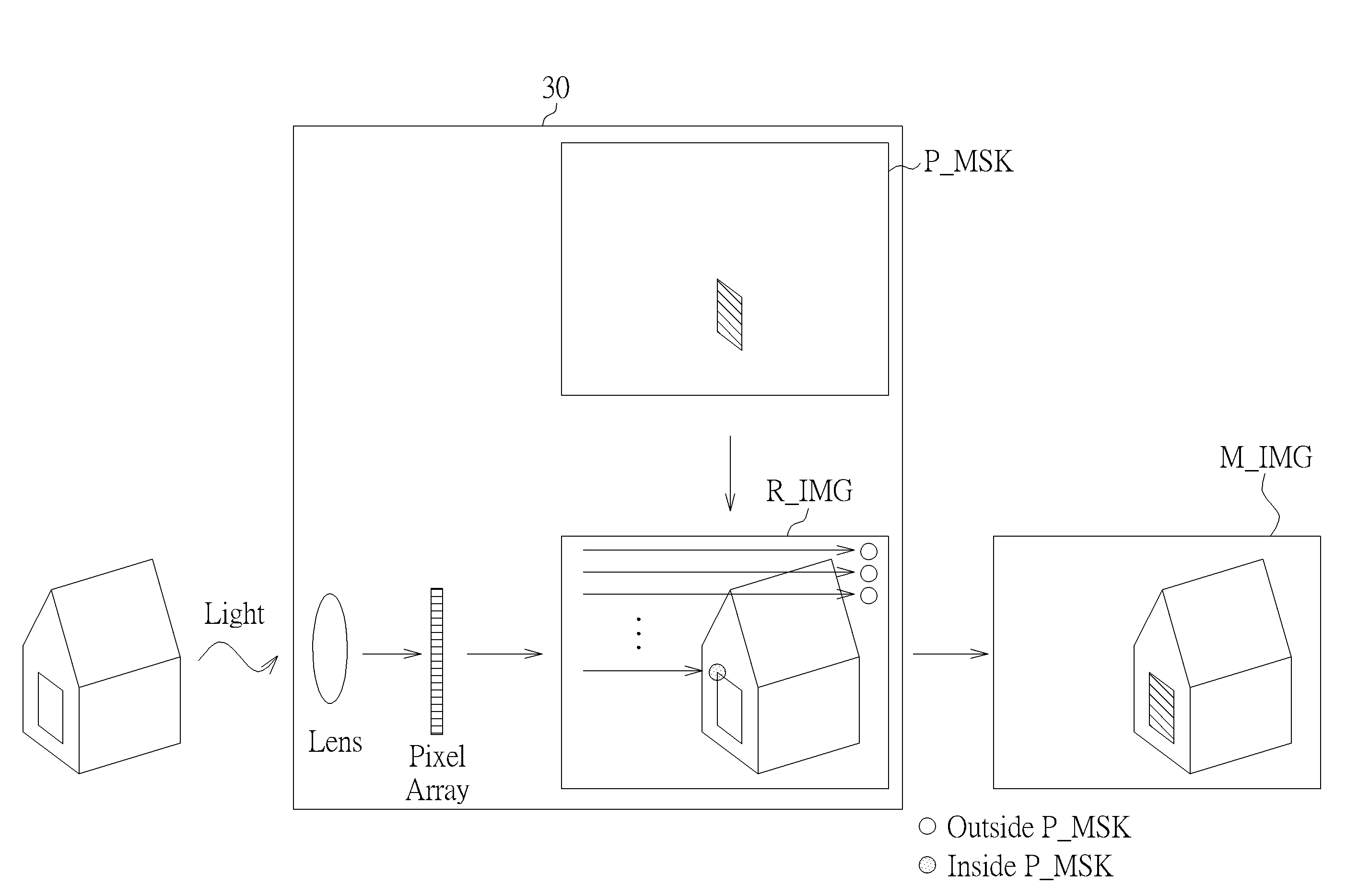
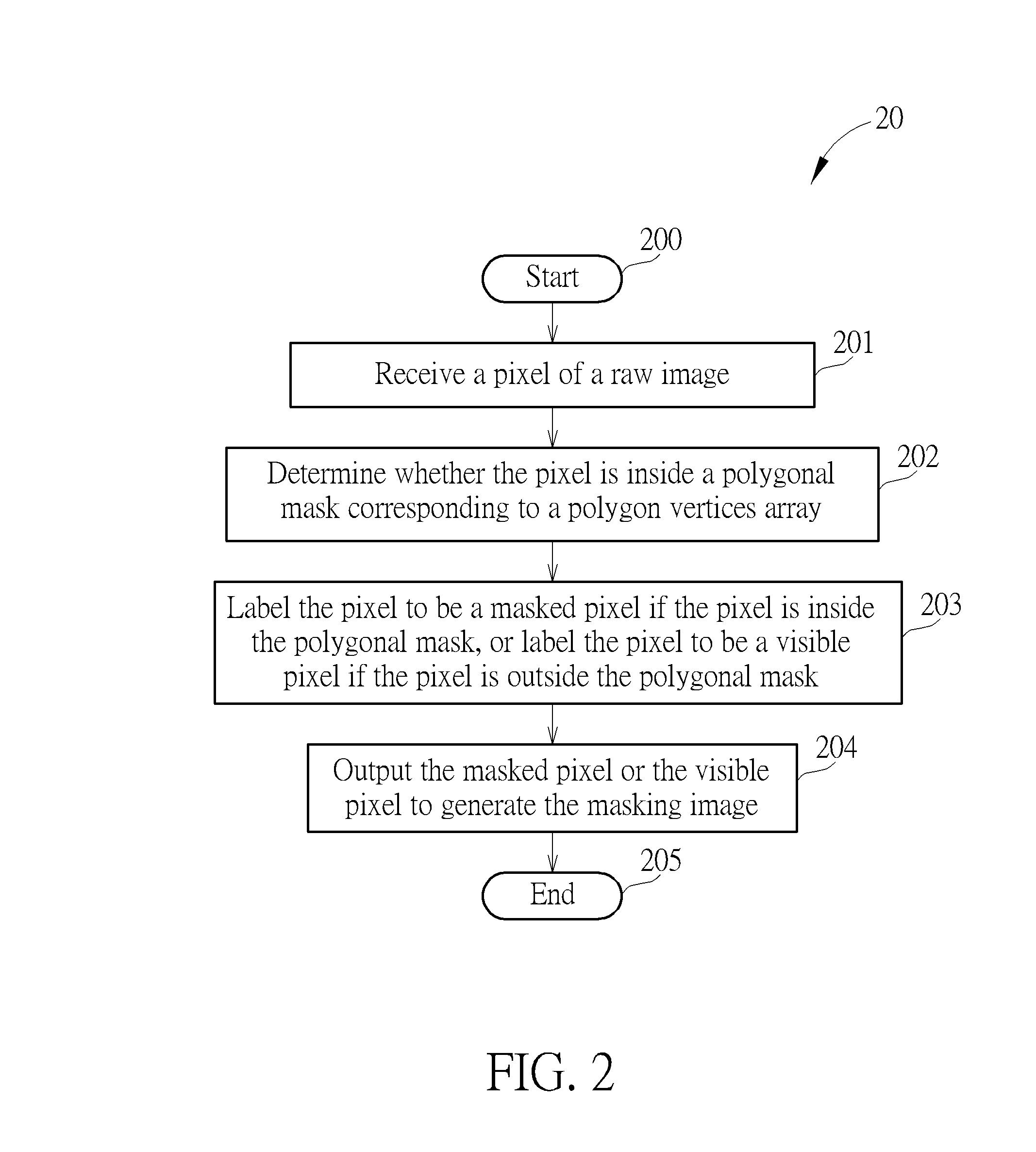
The present invention provides a method for generating a masking image using a polygonal mask. The method involves receiving a pixel of a raw image and a polygon vertices array corresponding to the polygonal mask. It then determines whether the pixel is inside the polygonal mask and labels it as a masked pixel. This allows for the output of either the masked or visible pixel to generate the masking image. Overall, this method enhances the precision and accuracy of masking images.

Problems solved by technology

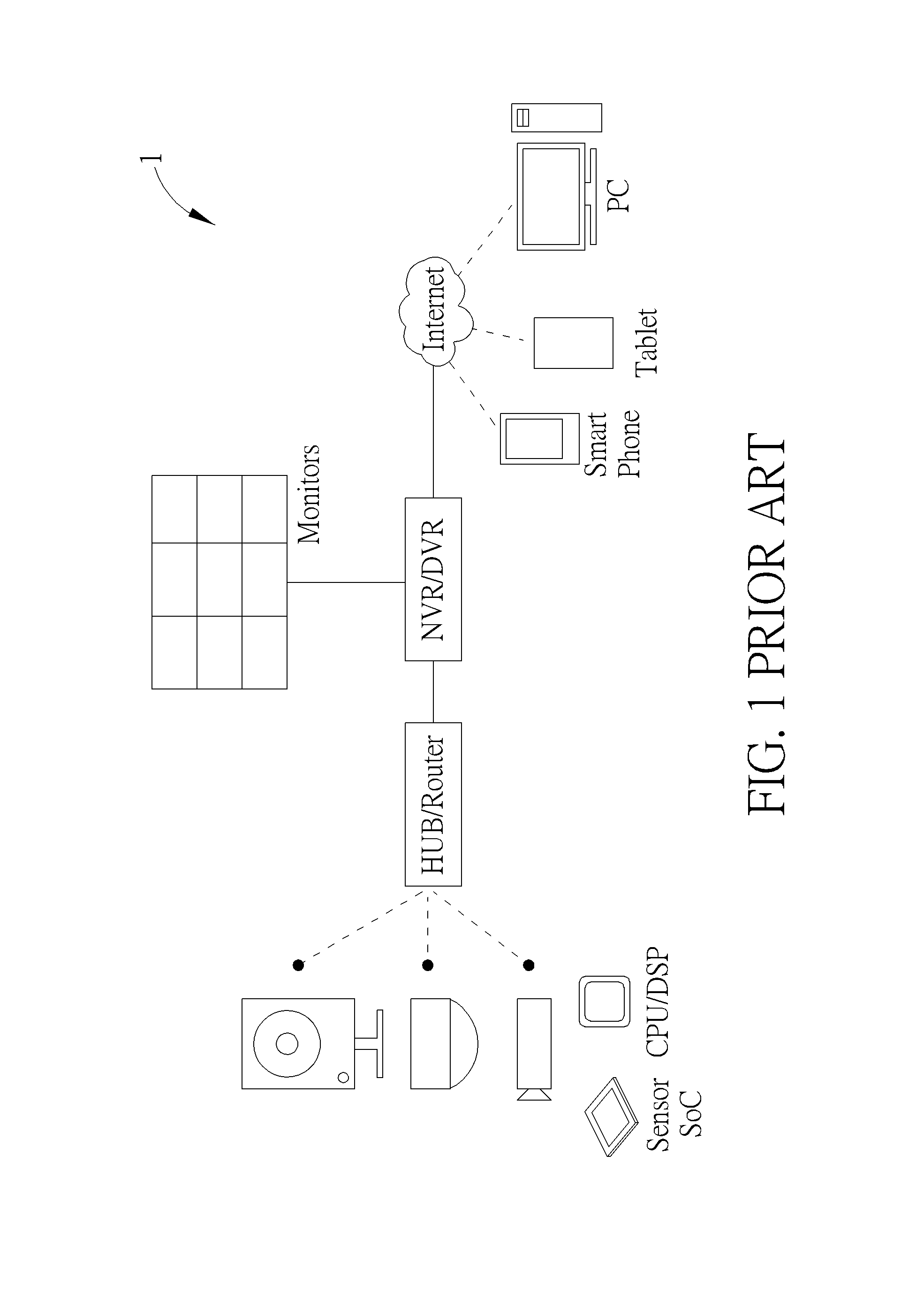
However, some regular variations happening in the enabled regions may cause a false alarm, for instance, braches and leaves swaying, traffic lights or other light sources changing.
The image mask having the irregular shape may have a good flexibility to be suitable for complicated geometric conversion; however, memory buffer(s) may be required in order to perform the complicated geometric conversion, which leads to a larger hardware area as well as a high hardware cost.
However, since the memory buffer(s) brings the larger hardware area and the high hardware cost, only the image mask having the regular shape is implemental on the front-end image capturing devices, which limits a flexibility of the surveillance system 1.

Method used


Image

  • Method for Generating Masking Image Using General Polygonal Mask
  • Method for Generating Masking Image Using General Polygonal Mask
  • Method for Generating Masking Image Using General Polygonal Mask

Examples


first embodiment

[0051]Please refer to FIG. 6, which illustrates a flowchart of a process 60 according to the present invention. The process 60 may be executed by the image sensor 30 to determine whether the pixel Q is inside or outside a polygonal mask having N edges. The process 60 includes the following steps:

[0052]Step 600: Start.

[0053]Step 601: Receive a pixel Q(X,Y) and a vertices array including vertices P0 to PN, and set a count C to be zero.

[0054]Step 602: Set a vertex Pi to be a start point PS(XS,YS), and a vertex Pi+1 to be a terminal point PT(XT,YT), wherein an indication i is 0, . . . , N.

[0055]Step 603: Check if a condition “YS≦Y and YT≦Y” or “YS>Y and YT>Y” is satisfied? Go to Step 609 if yes; go to Step 604 if no.

[0056]Step 604: Check if YT≧YS? Go to Step 605 if yes; go to Step 606 if no.

[0057]Step 605: Compute a cross product RC,[0058]wherein RC=(XT−X)*(YT−YS)−(XT−XS)*(YT−Y). Go to Step 607.

[0059]Step 606: Compute a cross product RC, wherein RC=(XT−XS)*(YT−Y)−(XT−X)*(YT−YS).

[0060]St...

second embodiment

[0079]Note that the process 60 is an example of the present invention, those skilled in the art may make modification or alterations accordingly, which is not limited. For example, please refer to FIG. 7, which illustrates a flowchart of a process 70 according to the present invention. The process 70 may be executed by the image sensor 30 to determine whether the pixel Q is inside or outside the polygonal mask having N edges. The process 70 includes the following steps:

[0080]Step 700: Start.

[0081]Step 701: Receive a pixel Q(X,Y) and a vertices array including vertices P0 to PN, and set a count C to be zero.

[0082]Step 702: Set a vertex Pi to be a start point PS(XS,YS), and a vertex Pi+1 to be a terminal point PT(XT,YT), wherein an indication i is 0, . . . , N.

[0083]Step 703: Check if a condition “YS≦Y and YT≦Y” or “YS>Y and YT>Y” is satisfied? Go to Step 708 if yes; go to Step 704 if no.

[0084]Step 704: Check if YT≧YS? Go to Step 705 if yes; go to Step 706 if no.

[0085]Step 705: Check ...

third embodiment

[0097]Please refer to FIG. 8, which illustrates a flowchart of a process 80 according to the present invention. The process 80 may be executed by the image sensor 30 to determine whether the pixel Q is inside or outside the polygonal mask having N edges. The process 80 includes the following steps:

[0098]Step 800: Start.

[0099]Step 801: Receive a pixel Q(X,Y) and a vertices array including vertices P0 to PN, and set a count C to be zero.

[0100]Step 802: Set a vertex Pi to be a start point PS(XS,YS), and a vertex Pi+1 to be a terminal point PT(XT,YT), wherein an indication i is 1, . . . , N.

[0101]Step 803: Check if Y≧YS ? Go to Step 804 if yes; go to Step 808 if no.

[0102]Step 804: Check if YT? Go to Step 805 if yes; go to Step 809 if no.

[0103]Step 805: Check if (XT−X)*(YT−YS) is greater than (XT−XS)*(YT−Y)? Go to Step 807 if yes; go to Step 809 if no.

[0104]Step 806: Check if (XT−XS)*(YT−Y) is greater than (XT−X)*(YT−YS)? Go to Step 807 if yes; go to Step 809 if no.

[0105]Step 807: Increa...


PUM


Abstract

A method for generating masking image using general polygonal mask includes receiving a pixel of a raw image and a polygon vertices array corresponding to a polygonal mask, determining whether the pixel is inside the polygonal mask, labeling the pixel to be a masked pixel if the pixel is inside the polygonal mask, or labeling the pixel to be a visible pixel if the pixel is outside the polygonal mask, and outputting the masked pixel or the visible pixel to generate the masking image.

Description

BACKGROUND OF THE INVENTION[0001]1. Field of the Invention[0002]The present invention relates to a method for generating a masking image using a general polygonal mask, and more particularly, to a method for generating the masking image using the general polygonal mask via determining relative locations between pixels and edges of the general polygonal mask.[0003]2. Description of the Prior Art[0004]Image masking refers to an image processing scheme that a certain region or an image mask is marked in an image to perform specific image processing or state configuration. The image processing, such as pixel values adjustment, and transparent, semi-transparent, opaque, and / or grid processing (s), may be performed to pixels inside the image mask, while pixels outside the image mask may remain the same or be processed with other image processing. As a result, a masking image may be generated by combining the pixels inside and outside the image mask.[0005]In practice, image masking is wide...

Claims


Application Information

Patent Timeline
IPC IPC(8): G06T11/40G06T15/40G06T3/00G06T1/00
CPCG06T11/40G06T1/0007G06T15/405G06T2207/10028G06T2200/12G06T2207/10004G06T3/0093G06T11/00G08B13/19606
Inventor KAO, JAU-HONGWANG, SHIANG-FEIWU, YI-JENLIN, CHIH-HUANGCHU, MIN-HUICHEN, HONG-CHULIOU, CHI-FAN
Owner NOVATEK MICROELECTRONICS CORP
Why Eureka
Try Eureka