Display device and manufacturing method thereof

a technology of a display face and a manufacturing method, which is applied in the direction of display/control unit casings, electric apparatus casings/cabinets/drawers, instruments, etc., can solve the problem of deterioration in display quality caused by foreign objects inserted into the inside of the display face, difficulty in manufacturing resin on the whole circumference of the steps of the gap, etc., to achieve high-reliability display

Active Publication Date: 2016-09-08
TIANMA MICRO ELECTRONICS CO LTD
View PDF7 Cites 17 Cited by
  • Summary
  • Abstract
  • Description
  • Claims
  • Application Information

AI Technical Summary

Benefits of technology

[0025]As an exemplary advantage according to the invention, it is possible to provide a high-quality and highly reliable display device since the gap can be securely filled even when there is variation in the gap between the bezel and the display panel through forming the first resin member on the display face and forming the second resin member formed to cover over the first resin member and the surface of the bezel opposing to the frontal panel.

Problems solved by technology

Due to the interface reflection, visibility of the displayed images becomes deteriorated greatly particularly under an open air environment.
Further, even with outer circumference lamination (referred to as “air gap bonding” for convenience hereinafter) of the square-shaped frontal panel and the display module with the air layer provided therebetween, deterioration in the display quality caused by foreign matters inserted into the inside of the display face is an issue.
However, there are following new issues (1) and (2) in the display device of the Related Technique 2.
Therefore, it is technically difficult in terms of manufacture to apply the resin on the whole circumference of the steps of the gap 72 with high precision.

Method used


Image

  • Display device and manufacturing method thereof
  • Display device and manufacturing method thereof
  • Display device and manufacturing method thereof

Examples


fifth exemplary embodiment

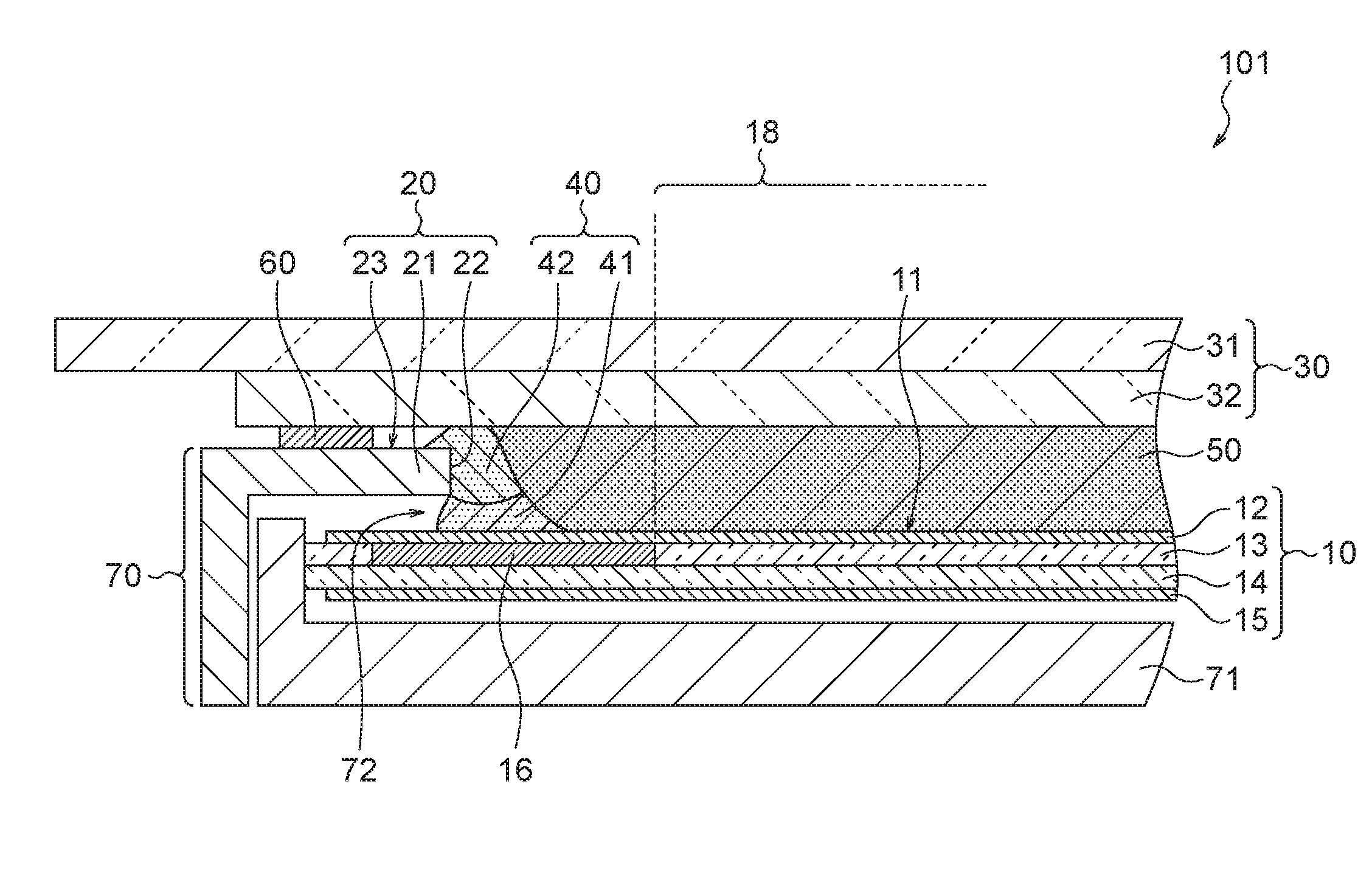
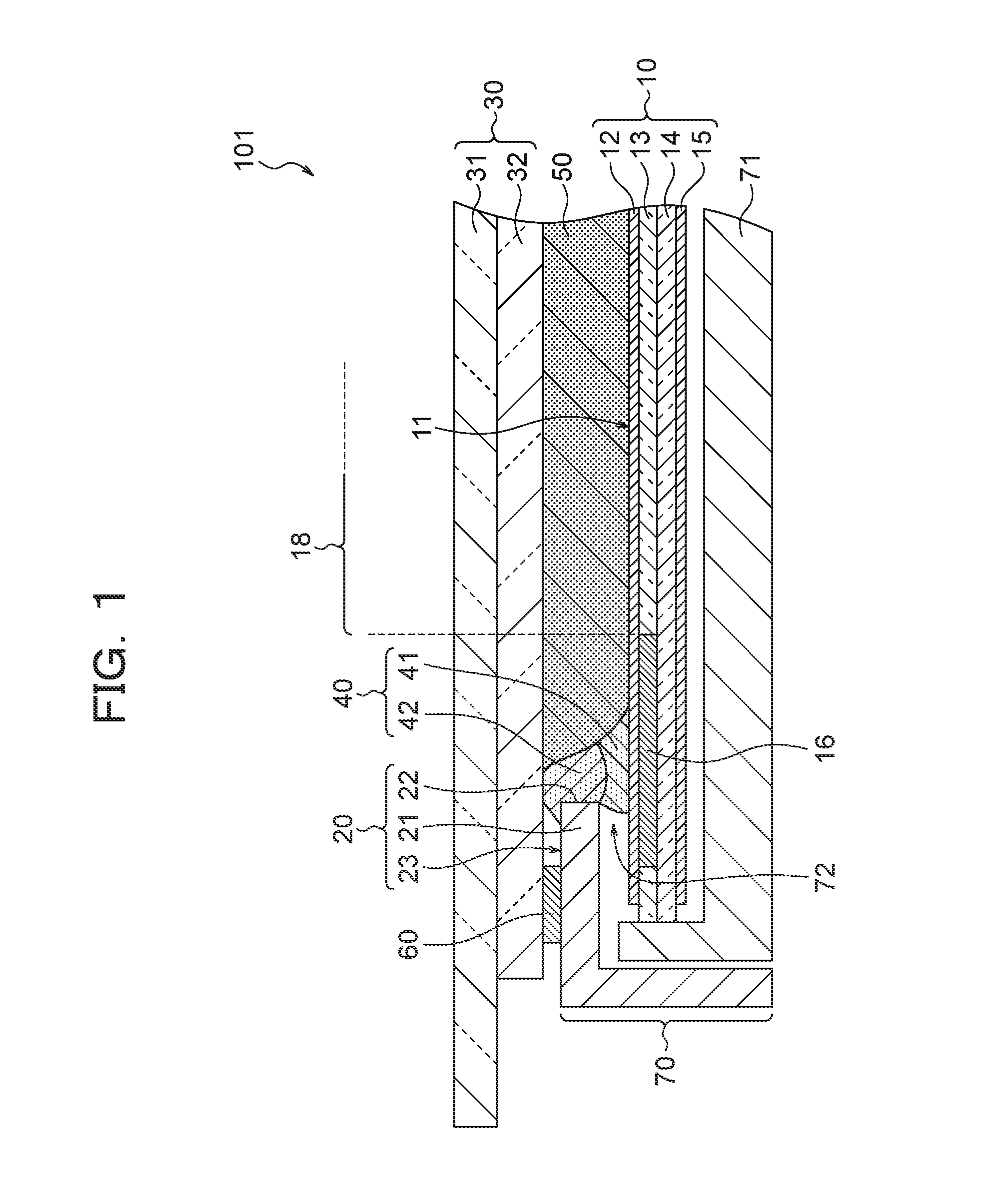
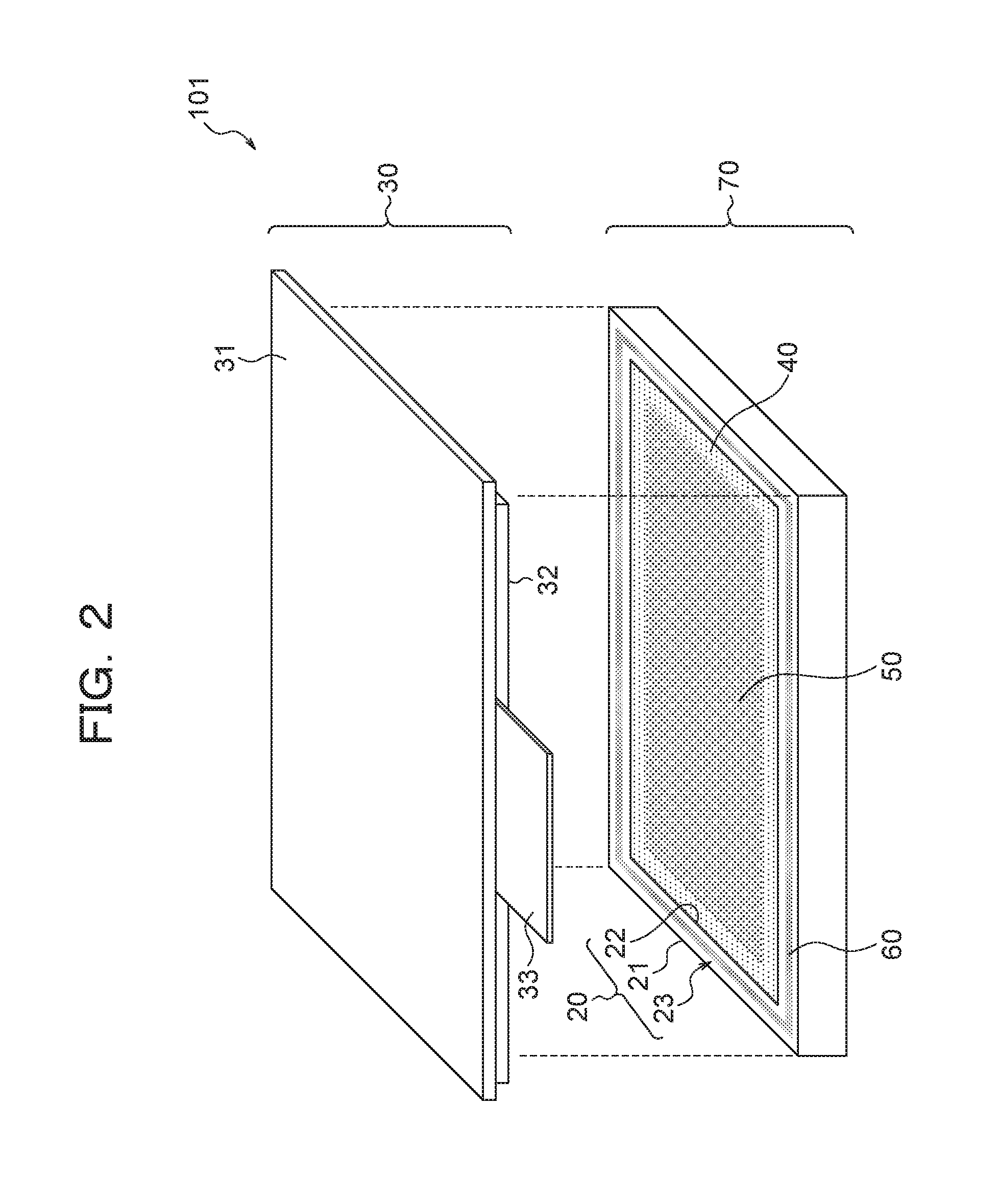
[0080]It is a feature of a display device 105 of the fifth exemplary embodiment that an adhesive member 61 is provided only in the four corners of the bezel 20 while the adhesive member 60 (FIG. 2) of the first exemplary embodiment is provided on the whole circumference of the bezel 20. The bezel 20 and the frontal panel 30 are in a square shape. That is, in the first to fourth exemplary embodiments, the adhesive member 61 provided to the outer circumference of the resin member 40 can also be formed only in a specific part without surrounding the whole circumference of the resin member 40. For example, in the fifth exemplary embodiment, the adhesive member 61 is disposed in an L-letter shape only in the four corners of the bezel 20 in a part to be laminated with the frontal panel 30 in the display device of the first exemplary embodiment. The adhesive member 61 is disposed in order to reinforce the adhesive force of the OCR 50 since the fifth exemplary embodiment employs optical-bon...

sixth exemplary embodiment

[0082]It is a feature of a display device 106 of the sixth exemplary embodiment that an adhesive member 62 is provided only in the four sides except for the four corners of the bezel 20 while the adhesive member 60 (FIG. 2) of the first exemplary embodiment is provided on the whole circumference of the bezel 20. That is, inversely from the case of the fifth exemplary embodiment, the sixth exemplary embodiment employs a structure with which the adhesive member 62 is not disposed only in the four corner parts of the bezel 20 in the display device of the first exemplary embodiment. In the first exemplary embodiment, the applied amount of the adhesive at the drawing bent points of the four corner parts of the bezel 20 tends to be large, so that the four corners of the bezel 20 are likely to be protruded up as a result. Thus, the pressure force applied when operating the frontal panel 30 transmits to the display panel 10 via the protruded part, so that ripple-like unevenness is likely to...

tenth exemplary embodiment

[0090]It is a feature of a display device 110 of the tenth exemplary embodiment that a second resin member 42b is formed only in a part of the whole circumference of the aperture end 22 while the second resin member 42 (FIG. 1) of the first exemplary embodiment is formed on the whole circumference of the aperture end 22. That is, the tenth exemplary embodiment is a case where: a first resin member 41b and the second resin member 42b (halfway-applied dam structure) are formed only in a part (e.g., a part where the gap 72 is maximum) of the bezel 20 (FIG. 16B); only the first resin member 41b (halfway-applied dam structure) is formed in the other part (FIG. 16A); and the frontal panel 30 is fixed by optical-bonding. The frontal panel 30 is smaller than the external shape of the display module 70 in the tenth exemplary embodiment, so that there is no adhesive member provided on the outer circumference of the resin member 40b. The tenth exemplary embodiment can be applied to cases where...


PUM


Abstract

To provide a display device of high quality and high reliability by securely sealing the gap between the bezel and the display panel even when variation is generated in the gap. The display device includes: a display panel including a display face; a bezel which includes a frame part and an aperture end that is on the inner side of the frame part, and covers the fringe of the display panel on the display face side by the frame part; a frontal panel provided by sandwiching the bezel on the display face side of the display panel; and a resin member provided along the whole circumference of the aperture end of the bezel. The resin member has a first resin member formed on the display face and a second resin member formed to cover over the first resin member and a surface of the bezel opposing to the frontal panel.

Description

CROSS-REFERENCE TO RELATED APPLICATION[0001]This application is based upon and claims the benefit of priority from Japanese patent application No. 2015-045078, filed on Mar. 6, 2015, the disclosure of which is incorporated herein in its entirety by reference.BACKGROUND OF THE INVENTION[0002]1. Field of the Invention[0003]The present invention relates to a display device such as a liquid crystal display device, for example, and to a manufacturing method thereof.[0004]2. Description of the Related Art[0005]Recently, the number of display devices each having a frontal panel such as a touch panel or a decorated panel on a liquid crystal display module as a device for display is increasing. A touch panel is an input interface component. A decorated panel is a reinforced glass or the like on which printing is applied for decoration for design qualities and protection of the display face.[0006]When the frontal panel is loaded on the liquid crystal display module, there is normally an air l...

Claims


Application Information

Patent Timeline
Patent Type & Authority Applications(United States)
IPC IPC(8): H05K5/00H05K9/00
CPCH05K9/0054H05K5/0017G02F1/1333G02F1/133308G02F1/13338G06F3/041G06F3/044G06F2203/04103G02F1/1341G06F1/1601G06F1/1637G06F2200/1612
Inventor FUJITA, AKIRANAKANISHI, FUTOSHIYOSHIDA, HITOSHISUZUKI, AKIRA
Owner TIANMA MICRO ELECTRONICS CO LTD
Why Eureka
Try Eureka