Eureka AIR delivers breakthrough ideas for toughest innovation challenges, trusted by R&D personnel around the world.

Reflector, projective display and projector

a projector and projector technology, applied in the field of projectors, can solve the problems of increasing fan size, aggravate noise problems, running counter to the reduction of projector size, weight and production cost, etc., and achieve the effect of improving reliability, and reducing the size and weight of the projector

Inactive Publication Date: 2005-03-03
MAXELL HLDG LTD
View PDF7 Cites 12 Cited by
  • Summary
  • Abstract
  • Description
  • Claims
  • Application Information

AI Technical Summary

Benefits of technology

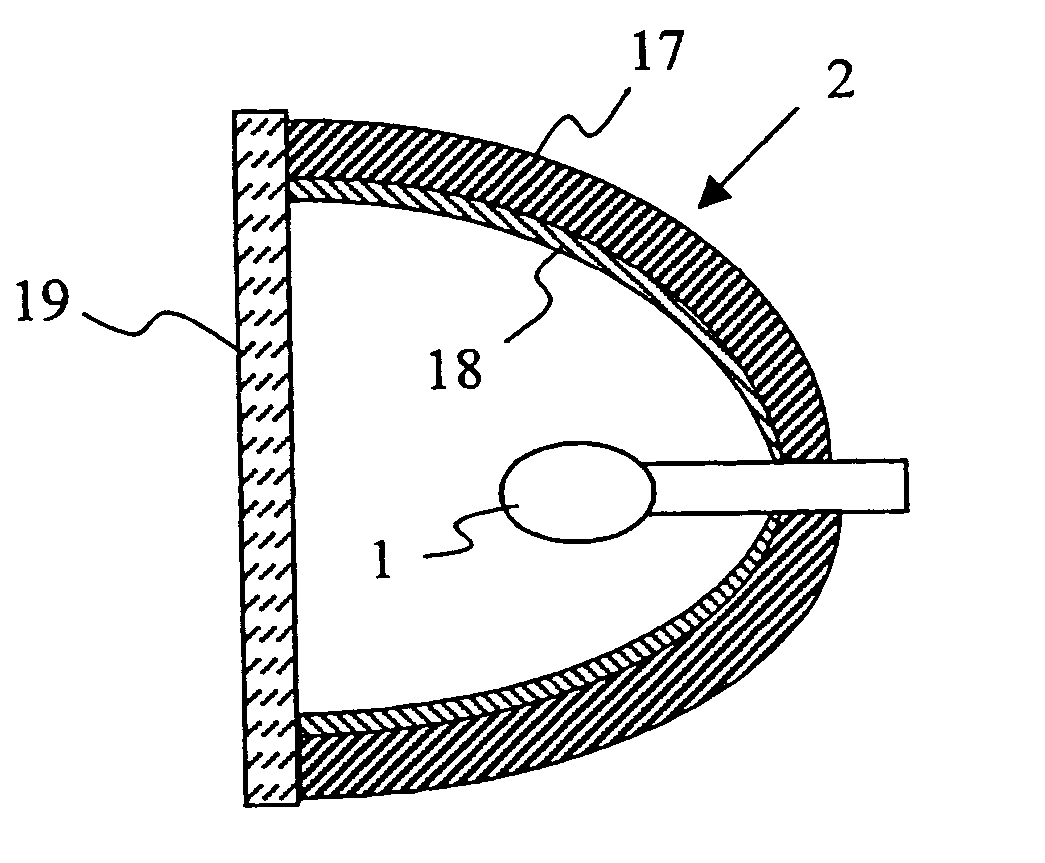
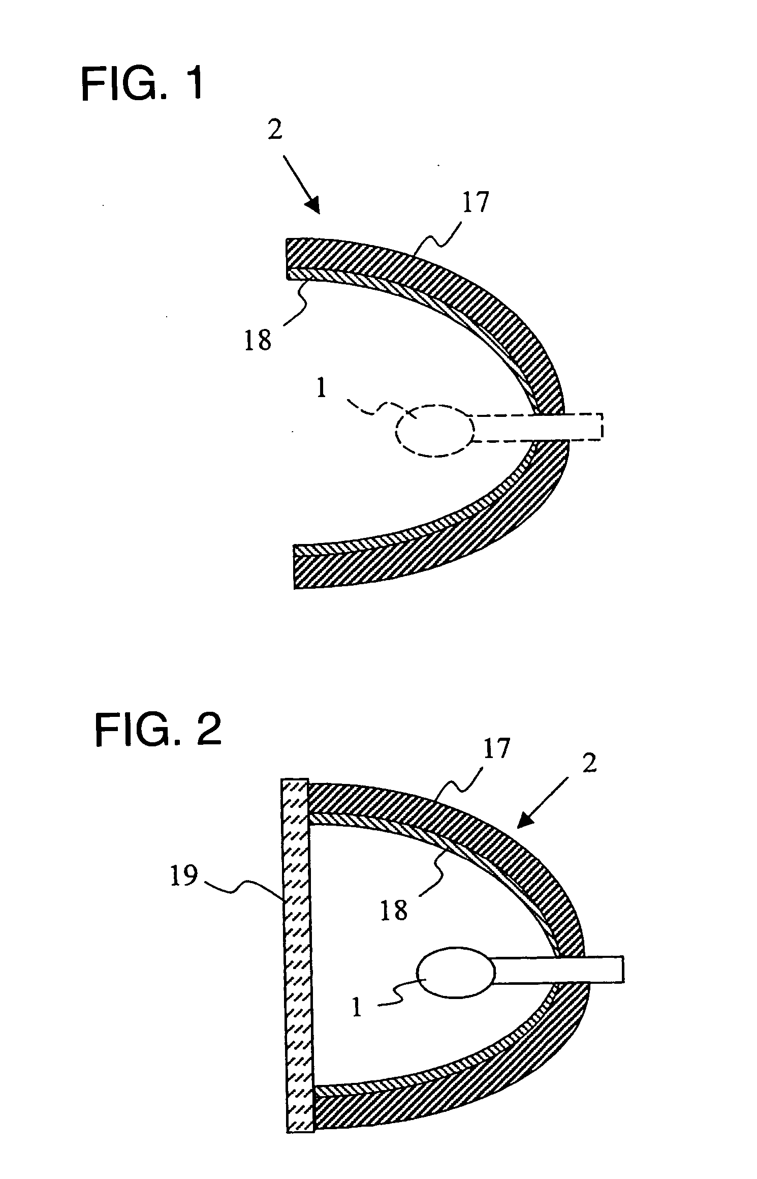
[0006] As discussed above, decreasing focal distance of the reflector 2 is one of the methods to decrease projector size. This, however, increases temperature of the reflector 2 more as it comes closer to the light-emitting section of the light source 1. At present, the reflector 2 is air-cooled by a fan. It is technically possible to control temperature rise at the reflector 2 by increasing fan size to increase its cooling capacity. Increasing fan size, however, runs counter to decreasing projector size, weight and production cost, and, at the same time, aggravates noise problems. It is therefore necessary to decrease light valve or reflector size in order to decrease reflector size and weight without increasing fan size.
[0008] It is an object of the present invention to provide a low-cost, high-quality reflector by solving the above problems.
[0011] The reflector of the present invention can decrease size and weight of the projective display, when used therefor, while improving its reliability. It can also decrease size and weight of the projector collecting beams from the light source in one direction, when used therefor. The glassy material for the present invention is also suitable for a light-transmitting plate to be positioned in front of a reflector.
[0012] The present invention provides a light, compact reflector of high resistance to heat. It can make the projective display and projector highly reliable, light and compact, when used therefor.

Problems solved by technology

Increasing fan size, however, runs counter to decreasing projector size, weight and production cost, and, at the same time, aggravates noise problems.
Moreover, it is necessary to crystallize crystal glass for a reflector after the reflector is formed into a shape, which should increase its production cost.
Still more, a reflector is exposed to changing heat while in service, which also produces irregularities on the surface as a result of difference in thermal expansion coefficient between the crystal and amorphous phases in the crystal glass.
This may deteriorate characteristics of the reflective layer provided on the glass.
Still more, further decreasing reflector size may be accompanied by uneven shape and distribution of the crystallites produced by the crystallization treatment to cause problems of deteriorated or fluctuated reflector strength.

Method used


Image

  • Reflector, projective display and projector
  • Reflector, projective display and projector
  • Reflector, projective display and projector

Examples


Embodiment Construction

[0023] The embodiments of the present invention are described by referring to the drawings.

[0024] First, the glass composition for the present invention is described. Each glass composition for the present invention is produced by the following procedure. The starting powders, each in a given quantity, were mixed with each other in a platinum crucible, and molten at 1600° C. in an electrical oven. After they were sufficiently molten, the resulting melt was stirred by a stirring blade. The melt was put in a graphite mold kept at around 400° C., and treated to dissipate strain, to prepare the glass block, from which the specimen for each analysis was prepared.

[0025] The glass characteristics analyzed were bending strength, thermal expansion coefficient and transition temperature. Bending strength was determined by the 3-point bending test carried out in accordance with JIS R-1601 with the specimen, 3 mm by 4 mm by 35 mm in size, under a crosshead speed of 0.5 mm / minute and span of 3...


PUM

PropertyMeasurementUnit
transition temperatureaaaaaaaaaa
crystallite diameteraaaaaaaaaa

Abstract

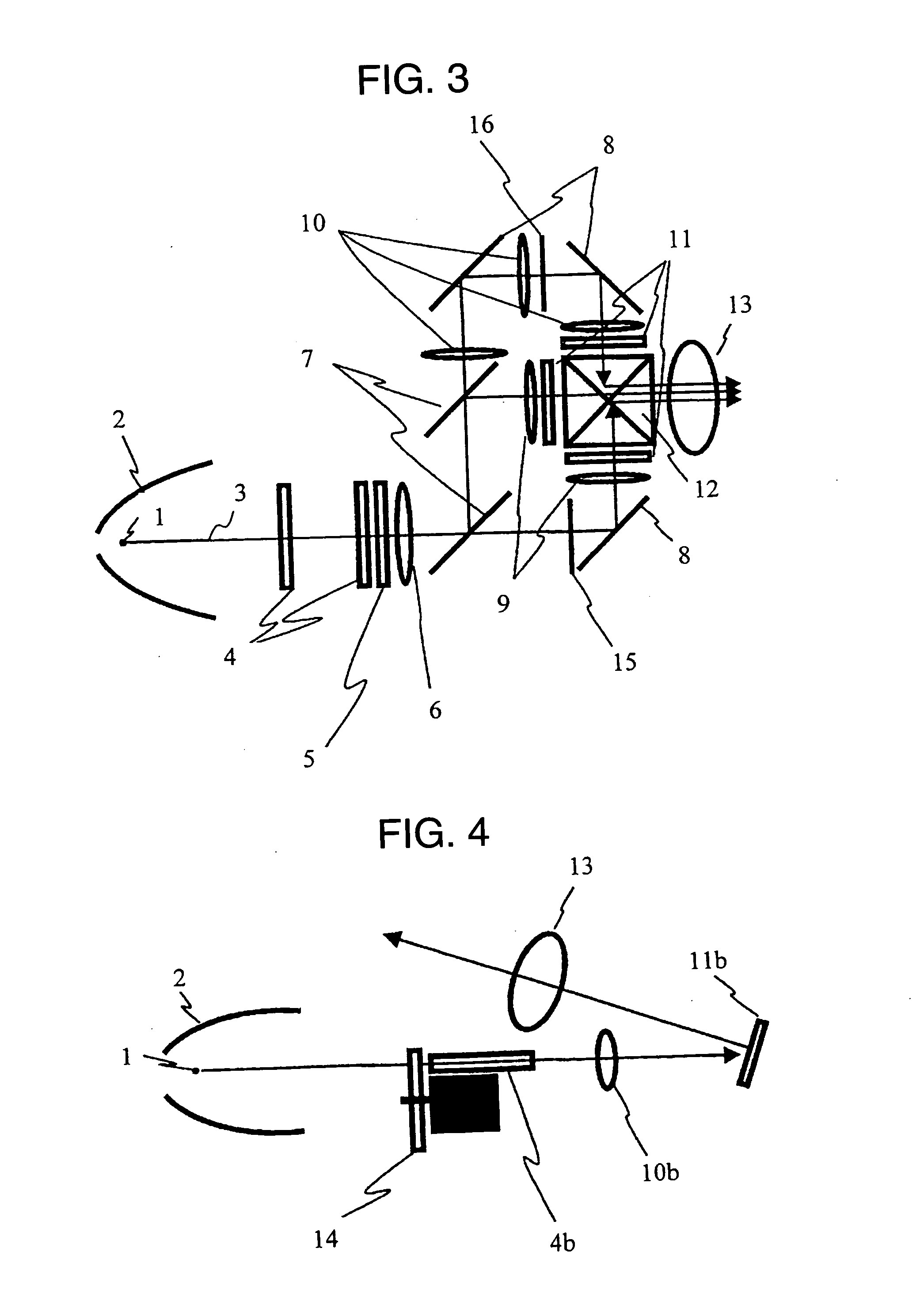
It is an object of the present invention to provide a reflector made of heat-resistant glass. It is another object of the present invention to provide a projective display which uses the reflector. A projector device having: a light source emitting white light; a reflector reflecting a light emitted from the light source; a light valve modulating illumination beam of light; and a projective lens projecting image light from the light valve, wherein the reflector is made of a glass containing SiO2 as a major ingredient and at least one rare-earth element selected from the group consisting of Sc, Y, La, Pr, Nd, Pm, Sm, Eu, Gd, Tb, Dy, Ho, Er, Tm, Yb and Lu, and the glass has a thermal expansion coefficient lower than 40×10−7 / ° C. and a transition temperature higher than 500° C.

Description

FIELD OF THE INVENTION [0001] The present invention relates to a reflector which reflects light fluxes (beam of light) emitted from a light source, a projective display and projector which can be widely used for back-projective TV sets and front-projective projectors. BACKGROUND OF THE INVENTION [0002] At present, projectors for business purposes have been widely spreading. Projective TV sets, which use a liquid-crystal display or the like, have been under development to replace conventional displays which project images displayed in a Braun tube onto a screen. A projective TV set, including a screen, needs a reflector of relatively large size, because (i) a projective TV set provides a relatively large space for devices, and (ii) a light source of long arc length (large light-emitting section) and reflector of long focal distance are frequently used to extend lamp life. On the other hand, it is particularly important to decrease size and weight of a projector for transportation. JP...

Claims


Application Information

Patent Timeline
Patent Type & Authority Applications(United States)
IPC IPC(8): G03B21/14F21S2/00F21V7/00F21V7/22F21Y101/00H04N5/74
CPCC03C3/095H04N5/74F21V7/22F21S48/1394F21S41/37F21V7/24F21V7/28
Inventor MIYATA, MOTOYUKIYATSU, MASAHIKOAKATA, HIROYUKIDEGUCHI, MASAHARUWATANABE, KATSUYUKINAITOU, TAKASHIHIRATA, KOJI
Owner MAXELL HLDG LTD
Why Eureka
Eureka Blog
Learn More