Liquid ejecting head and method of manufacturing liquid ejecting head

a liquid ejecting head and liquid ejecting technology, which is applied in the direction of printing, inking apparatus, etc., can solve the problems of difficult to decrease the resistance of the wire without changing, and the wire area has become large, so as to suppress the change of the electrical characteristics of the wire, high reliability, and suppress the effect of the wire breaking

Active Publication Date: 2016-09-15
SEIKO EPSON CORP
View PDF15 Cites 14 Cited by
  • Summary
  • Abstract
  • Description
  • Claims
  • Application Information

AI Technical Summary

Benefits of technology

[0020]According to this configuration, it is possible to suppress a change in the electrical characteristics of a wire due to environmental changes. Moreover, it is possible to suppress breakage of a wire due to migration or the like. Consequently, it is possible to provide a liquid ejecting head having high reliability.

Problems solved by technology

However, to date, when the width of the wire has been increased in order to lower the resistance of the wire, the wire area has become large.
Consequently, it has been difficult to decrease the resistance of the wire without changing the size of the sealing plate.

Method used


Image

  • Liquid ejecting head and method of manufacturing liquid ejecting head
  • Liquid ejecting head and method of manufacturing liquid ejecting head
  • Liquid ejecting head and method of manufacturing liquid ejecting head

Examples


Embodiment Construction

[0030]Hereinafter, modes for carrying out the invention will be described with reference to the accompanying drawings. The embodiment described below is a preferred embodiment of the invention, and even though various limitations are imposed, the scope of the invention is not intended to be limited to these limitations unless there is a particular description that limits the invention in the following description. Moreover, hereinafter, an ink jet printer (hereinafter, printer), which is one type of liquid ejecting apparatus mounted with an ink jet recording head (hereinafter, recording head), which is one type of liquid ejecting head, according to the invention will be described as an example.

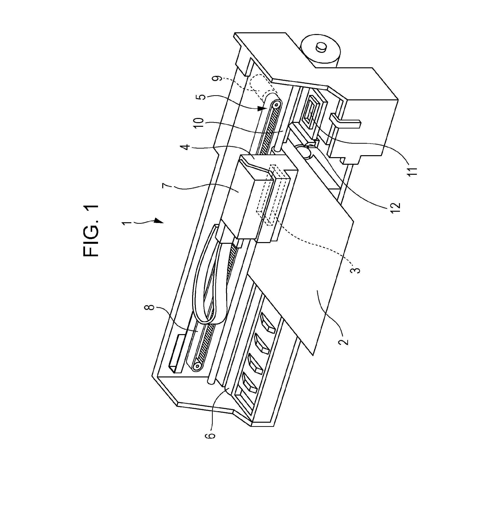
[0031]The structure of a printer 1 will be described with reference to FIG. 1. The printer 1 is an apparatus that performs recording of an image or the like by ejecting ink (a type of liquid) onto a surface of a recording medium 2 (a type of landing target) such as recording paper. The printer...


PUM


Abstract

A liquid ejecting head and a method of manufacturing the liquid ejecting head are provided. The liquid ejecting head has a pressure chamber forming substrate that includes a plurality of piezoelectric elements and that is connected to a first surface of a sealing plate, a driver IC that outputs signals that drive the piezoelectric elements and that is provided on a second surface of the sealing plate that is on the opposite side to the first surface, and a power supply wire that supplies electrical power to the piezoelectric elements, that is formed in the second surface of the sealing plate, and that has at least one portion thereof embedded in the sealing plate and a surface thereof exposed on the second surface side.

Description

[0001]The entire disclosure of Japanese Patent Application No: 2015-046946, filed Mar. 10, 2015 is expressly incorporated by reference herein in its entirety.BACKGROUND[0002]1. Technical Field[0003]The present invention relates to a liquid ejecting head including a wiring substrate on which wires to be connected to a driver IC have been formed and a method of manufacturing the liquid ejecting head.[0004]2. Related Art[0005]As liquid ejecting apparatuses including liquid ejecting heads, for example, there exist image recording devices such as ink jet printers, ink jet plotters and the like, however, recently, liquid ejecting apparatuses have been applied to various manufacturing devices by utilizing their advantage of being able to make a minute amount of liquid precisely land onto a designated position. For example, liquid ejecting apparatuses have been applied to display manufacturing devices that manufacture color filters of liquid crystal displays and the like, electrode forming ...

Claims


Application Information

Patent Timeline
Patent Type & Authority Applications(United States)
IPC IPC(8): B41J2/14B41J2/16
CPCB41J2/1433B41J2002/14491B41J2/1625B41J2/162B41J2/14B41J2/14233B41J2/161B41J2/1623B41J2/1628B41J2/1629B41J2/1631B41J2/1632B41J2/1635B41J2/1642B41J2/1643B41J2/1646B41J2002/14362B41J2202/18B41J2002/1425
Inventor TANAKA, SHUICHI
Owner SEIKO EPSON CORP
Why Eureka
Try Eureka