Vehicle Navigation Methods, Systems and Computer Program Products

a vehicle navigation and computer program technology, applied in the field of vehicle navigation methods, systems and computer program products, can solve the problems of generating synthetic images representing features and obstacles, reducing runway access, and reducing weather-related delays and cancellations.

Active Publication Date: 2016-09-15
VU SYST LLC
View PDF5 Cites 14 Cited by
  • Summary
  • Abstract
  • Description
  • Claims
  • Application Information

AI Technical Summary

Benefits of technology

[0020]According to other embodiments of the present invention, a method for creating a video image from a plurality of image streams includes receiving a video image from each of a plurality of video image sensors, wherein at least one of the plurality of video image sensors is mounted to a vehicle; pre-enhancing at least one of the plurality of video images; and combining the plurality of video images to produce an output video image. In some embodiments, pre-enhancing includes applying a super-resolution technique to a video image to increase the resolution of the video image.
[0022]In the field of aviation, embodiments of the present invention are particularly advantageous because runways and obstacles on approach can be seen by pilots regardless of the visibility conditions. As such weather-related delays and cancellations may be reduced, access to more runways worldwide may increase, and air travel safety may be increased.

Problems solved by technology

The images produced by IR and UV cameras, however, look very strange to humans, which make IR and UV images more difficult to understand and process than visible light images, which humans are accustomed to seeing.
For example, one image may have valuable information but is so bright (or “hot”) that by the time it is scaled down to avoid washing out the output image, the desired detail is also lost.
One problem, however, is that even the synthetic images representing features and obstacles are usually generated from image data provided by image sensors.
If the image sensors cannot detect or distinguish the important features or obstacles, the imagery provided by the sensor on the HUD may be of little value to the pilot.

Method used


Image

  • Vehicle Navigation Methods, Systems and Computer Program Products
  • Vehicle Navigation Methods, Systems and Computer Program Products
  • Vehicle Navigation Methods, Systems and Computer Program Products

Examples


Embodiment Construction

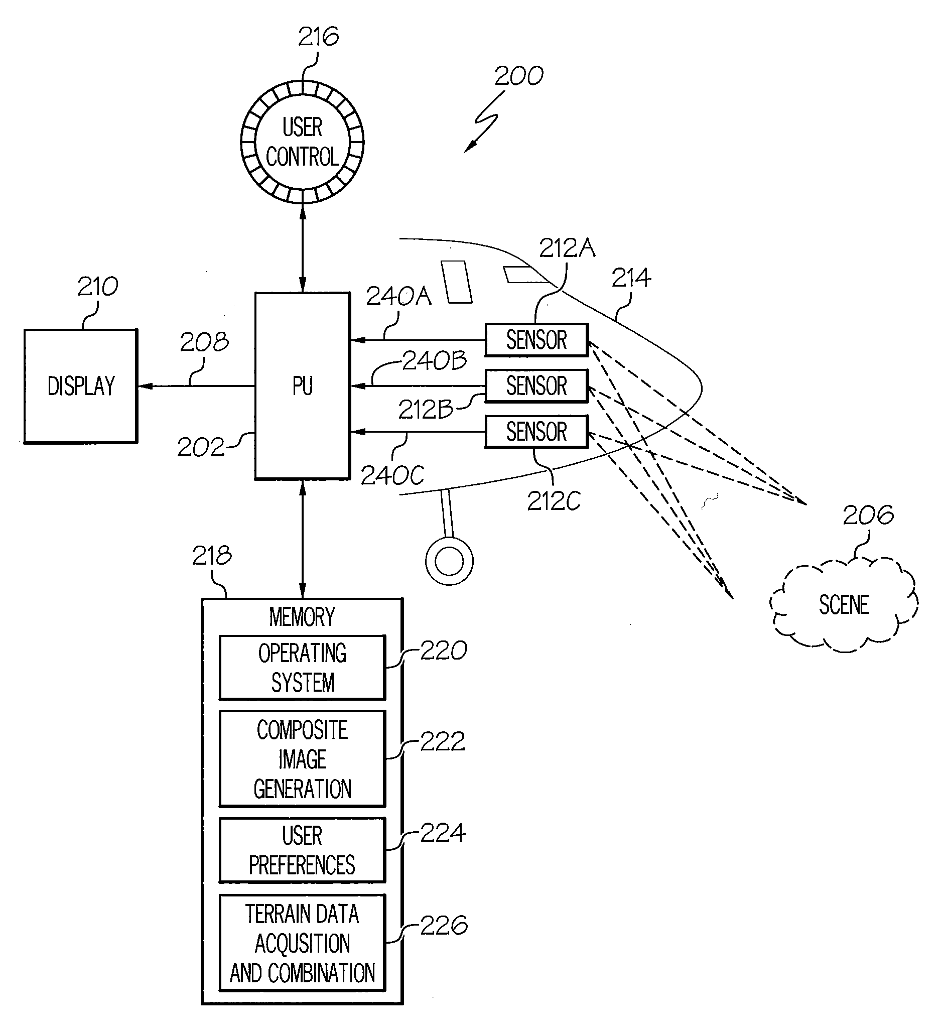
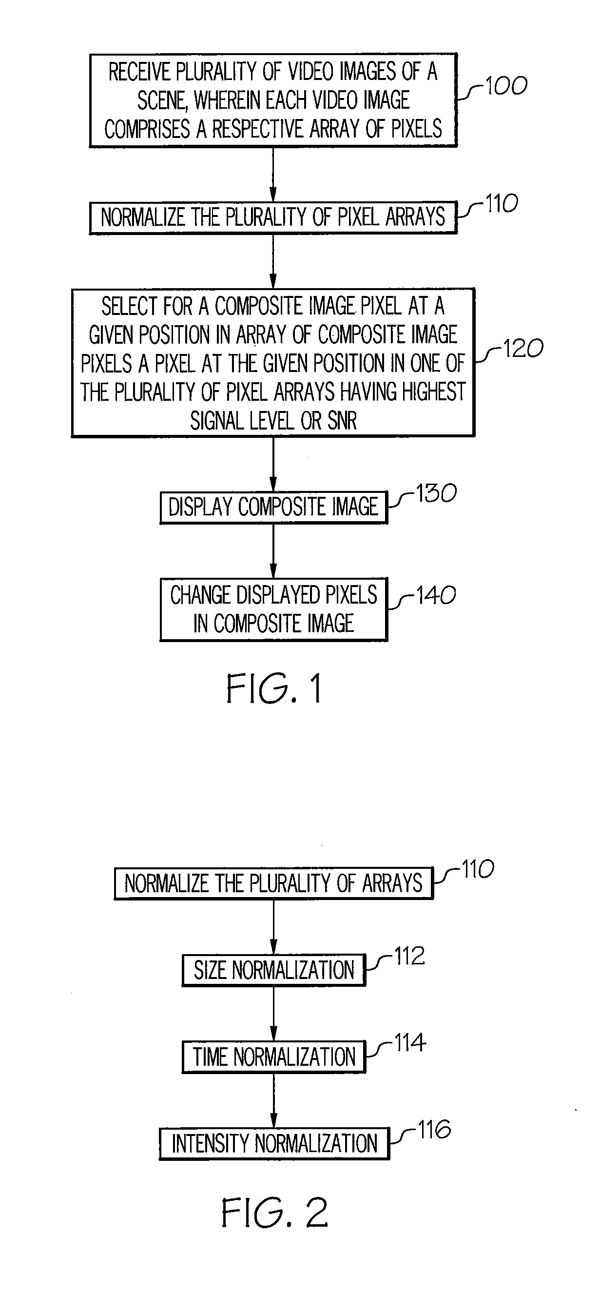
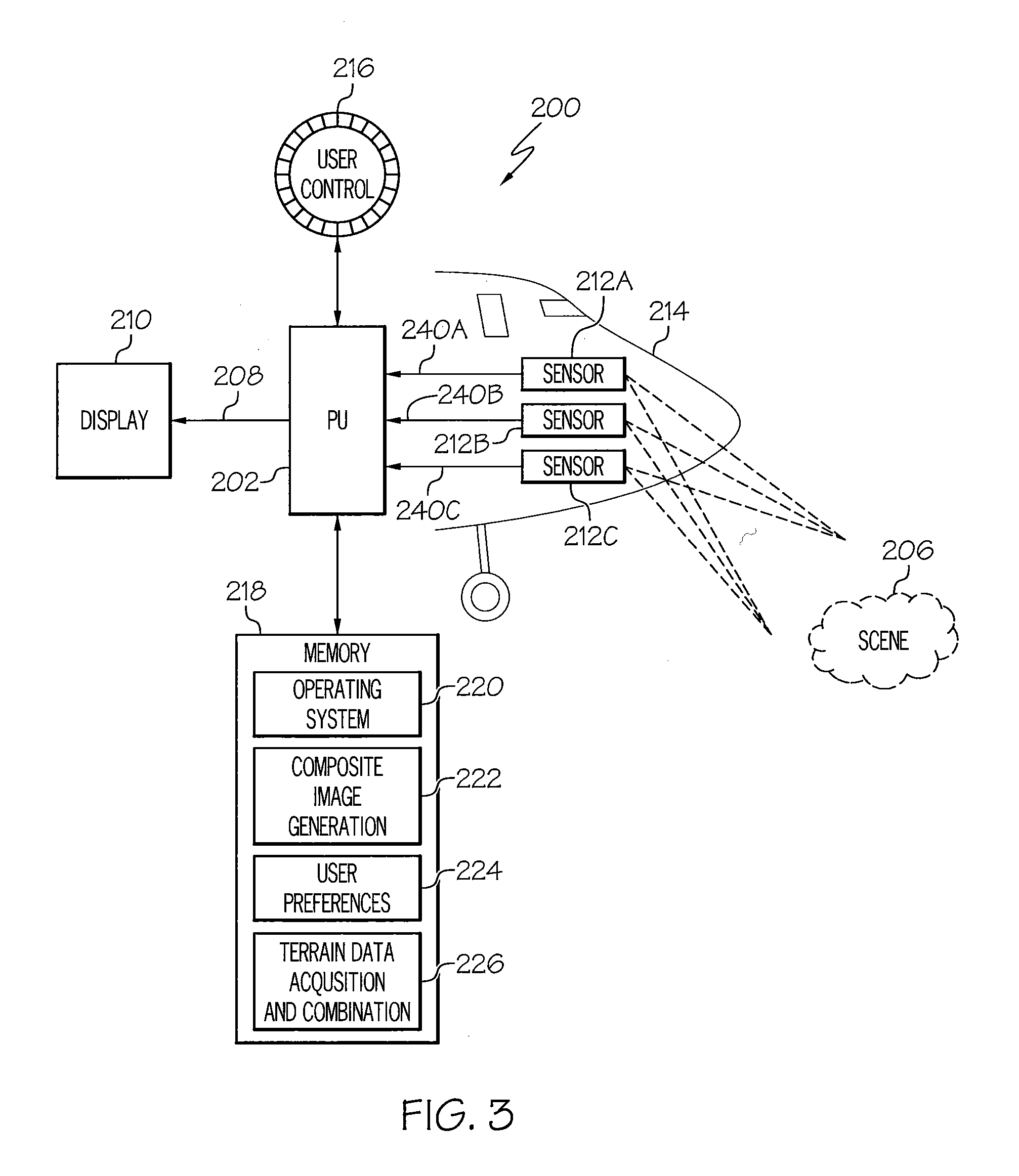
[0034]The present invention will now be described more fully hereinafter with reference to the accompanying figures, in which embodiments of the invention are shown. This invention may, however, be embodied in many different forms and should not be construed as limited to the embodiments set forth herein. Like numbers refer to like elements throughout. In the figures, certain components or features may be exaggerated for clarity. In addition, the sequence of operations (or steps) is not limited to the order presented in the figures and / or claims unless specifically indicated otherwise. Features described with respect to one figure or embodiment can be associated with another embodiment or figure although not specifically described or shown as such.

[0035]The terminology used herein is for the purpose of describing particular embodiments only and is not intended to be limiting of the invention. As used herein, the singular forms “a”, “an” and “the” are intended to include the plural f...


PUM


Abstract

Vehicle navigation methods, systems and computer program products are provided that create a composite video image of a scene from video images of the scene generated by a plurality of video image sensors. The video image from each image sensor includes a respective array of pixels. The composite video image is created by selecting for a composite image pixel at a given position in an array of composite image pixels a pixel at the given position from one of the respective pixel arrays having the highest signal level or highest signal-to-noise ratio. The selecting is repeatedly performed for a plurality of given positions in the array of composite image pixels. The composite video image can be displayed via a display, such as a head-up display utilized in a vehicle.

Description

RELATED APPLICATION[0001]This application claims the benefit of and priority to U.S. Provisional Patent Application No. 62 / 132,291 filed Mar. 12, 2015, the disclosure of which is incorporated herein by reference as if set forth in its entirety.FIELD OF THE INVENTION[0002]The present invention relates generally to imaging and, more particularly, to imaging methods, systems and computer program products.BACKGROUND OF THE INVENTION[0003]Moving vehicles, such as aircraft, watercraft, and ground-based vehicles (herein referred to generically as “vehicles”) often must operate in conditions of limited visibility due to rain, fog, glare, darkness, and other environmental conditions that prevent a clear view of the surrounding scene. As used herein, the term “scene” refers to a view of an object or of a volume from a particular point and looking in a particular direction in three-dimensional space. Thus, the “scene” visible to a pilot through a cockpit window will change whenever the attitud...

Claims


Application Information

Patent Timeline
Patent Type & Authority Applications(United States)
IPC IPC(8): B64D43/00G02B27/01H04N5/265H04N7/18H04N5/247H04N5/77
CPCB64D43/00H04N5/247H04N5/77G02B2027/0147H04N7/181G02B27/0101G02B2027/014H04N5/265G02B27/01H04N23/90
Inventor CONNOR, SIDNEY A.STEVENS, J. STEDMAN
Owner VU SYST LLC
Why Eureka
Try Eureka