Blade stabiliser tool for drill string

a stabiliser tool and drill string technology, applied in the direction of drilling rods, drilling pipes, drilling casings, etc., can solve the problems of severe failure and severe damage to the blocks that secure the blade to the body

Active Publication Date: 2016-09-15
EURON DRILLING PROJECTS BV
View PDF2 Cites 7 Cited by
  • Summary
  • Abstract
  • Description
  • Claims
  • Application Information

AI Technical Summary

Benefits of technology

[0017]As blades are replaceable, they can be easily and quickly replaced on the rig site. This feature enables the stabiliser tool to be redressed or repaired at the rig site, enabling worn out and damaged stabiliser blades to be quickly replaced and eliminating the necessity to transport worn or damaged stabilisers to a specialized workshop for repair. Blades of different sizes can be fitted to the cylindrical body, eliminating the necessity to have additional under-gauge stabiliser tools on the rig site. The capacity to replace damaged or worn stabiliser blades on location, and to mount on the stabiliser tool stabiliser blades of different sizes greatly reduces the inventory of stabiliser tools required on the drilling location. The capital savings on daily rental charges, transportation costs, and the reduction in storage space, adds to the technical advantage of the invention.

Problems solved by technology

Although this configuration has shown to be working in a satisfactory manner in normal circumstances, it led to severe failure when the forces into play reach certain threshold values.
In case of impact forces higher than certain threshold values some of the blades can be forced out of their recesses and the blocks that secure the blade to the body can suffer severe damages.

Method used


Image

  • Blade stabiliser tool for drill string
  • Blade stabiliser tool for drill string
  • Blade stabiliser tool for drill string

Examples


Embodiment Construction

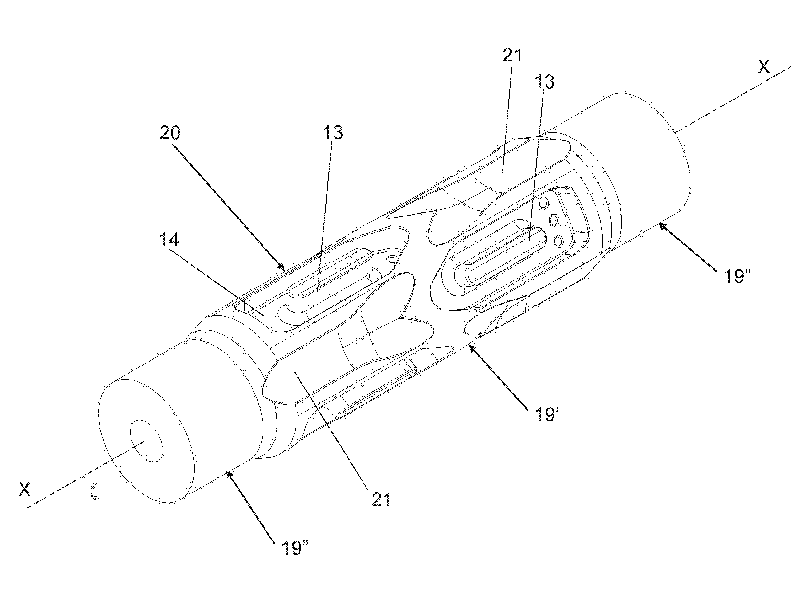
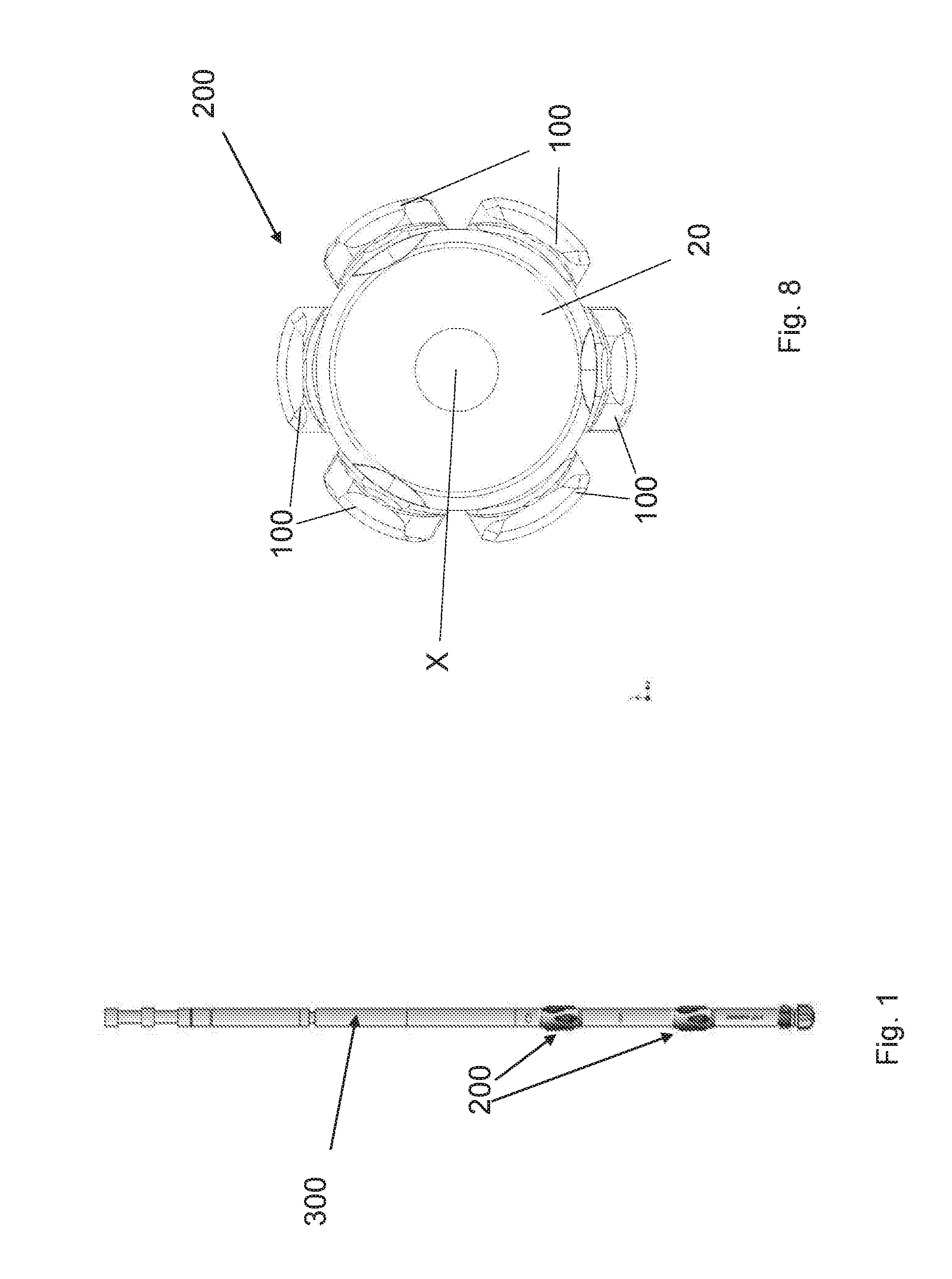
[0029]A stabiliser tool 200 according to the invention is shown in FIG. 1 mounted in two positions along a drill string 300. With particular reference to the FIGS. 3 to 9 the stabiliser tool 200 of the invention comprises six stabiliser blades 100 made from mild steel. The stabiliser blades are preferably all of identical shape and we describe only one stabiliser blade.

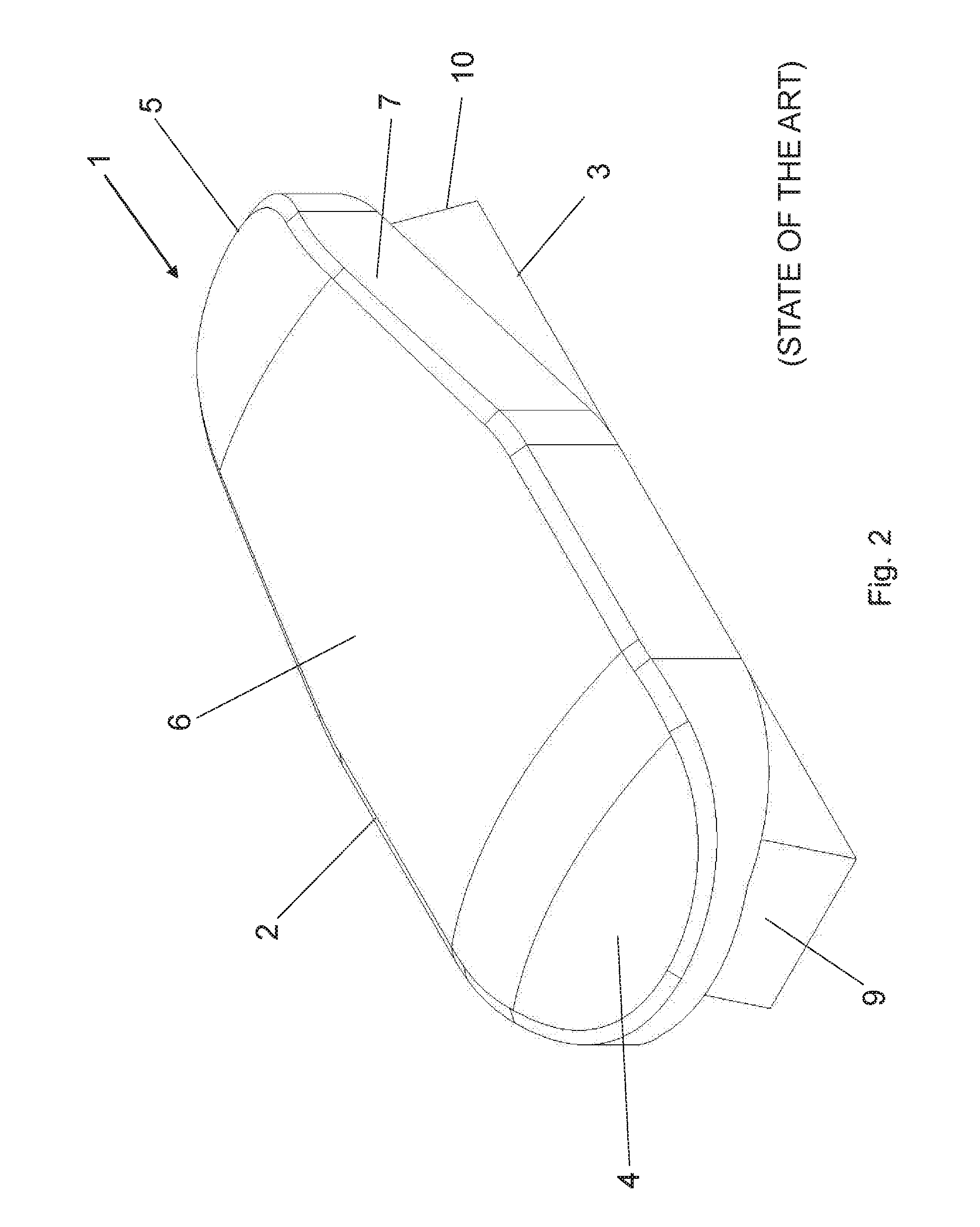
[0030]The stabiliser blade 100 is monolithic and has an elongated shape defining a longitudinal axis. It comprises an upper stabilizing part 2, placed radially distally from the longitudinal axis X of the stabilizer tool 200 when mounted, and a lower mounting part 3, placed radially proximally from the longitudinal axis of the stabilizer tool when mounted. The upper stabilizing part 2 has the shape of a wing and comprises a front section 4, a back section 5 and a central section 11. The central section 11 has a width perpendicularly to the longitudinal axis of magnitude equal to the width of the lower mounting part 3 ...


PUM


Abstract

A drilling string stabiliser tool comprises a cylindrical body and a plurality of stabiliser blades mounted on the outer surface of the cylindrical body. The stabiliser blades have an elongated shape and a monolithic structure with an upper stabilizing part and a lower mounting part. Between each two adjacent blades there can optionally be a hydrodynamic flute for improving the flow of liquid and cuttings during drilling and tripping.

Description

CROSS REFERENCE TO RELATED APPLICATIONS[0001]This application claims priority to EP patent application No. 15159006.4, filed Mar. 13, 2015, which is incorporated herein by reference thereto.FIELD OF THE INVENTION[0002]The present invention relates to a blade stabiliser tool used for stabilizing the operation of a drill string when drilling oil, gas, or geothermal wells.STATE OF THE ART[0003]In directional drilling it is very important to maintain full control of the operations. To maintain control of the drill string, it is known to use a certain number, normally 2 or 3, of so called drilling stabilisers placed in the bottom hole assembly. An example of a drilling string with a bottom hole assembly configuration with 2 stabilisers is shown in FIG. 1. The primary function of the stabilisers in the drilling string is to support and stabilise the bottom hole assembly in the borehole through the earth surface. The design of the stabiliser blades should be such that they reduce both fric...

Claims


Application Information

Patent Timeline
Patent Type & Authority Applications(United States)
IPC IPC(8): E21B17/10
CPCE21B17/1078
Inventor NEWMAN, MICHAEL THOMASKOK, RICARDO
Owner EURON DRILLING PROJECTS BV
Why Eureka
Try Eureka