Ball seat and ball joint

a ball seat and ball joint technology, applied in the field of ball seats and ball joints, can solve the problems of inability to efficiently assembly the ball joint, inability to carry out the assembly process, and inability to reduce the load

Inactive Publication Date: 2016-09-15
SOMIC ISHIKAWA INC
View PDF25 Cites 5 Cited by
  • Summary
  • Abstract
  • Description
  • Claims
  • Application Information

AI Technical Summary

Benefits of technology

[0018]Specifically, it is preferable that a tip of a shaft-shaped stud has a ball stud with a spherical ball part, the ball seat, and a socket for housing a holder of the ball seat so that the holder is pushed to the ball part side by the inner surface to be deformed. With a ball joint with this structure, the same effect as the aforementioned ball seat can be expected.

Problems solved by technology

Therefore, when the ball seat is pressed into a socket and a side of the ball seat is deformed to the ball part side, a load concentrates at a corner of the groove to sometimes cause overload and a damage due to stress concentration.
Accordingly, there has been a problem with a ball seat known to the inventors that a process of assembling a ball joint is cumbersome and complicated and that efficient assembly is not possible due to low yield.

Method used


Image

  • Ball seat and ball joint
  • Ball seat and ball joint
  • Ball seat and ball joint

Examples


Embodiment Construction

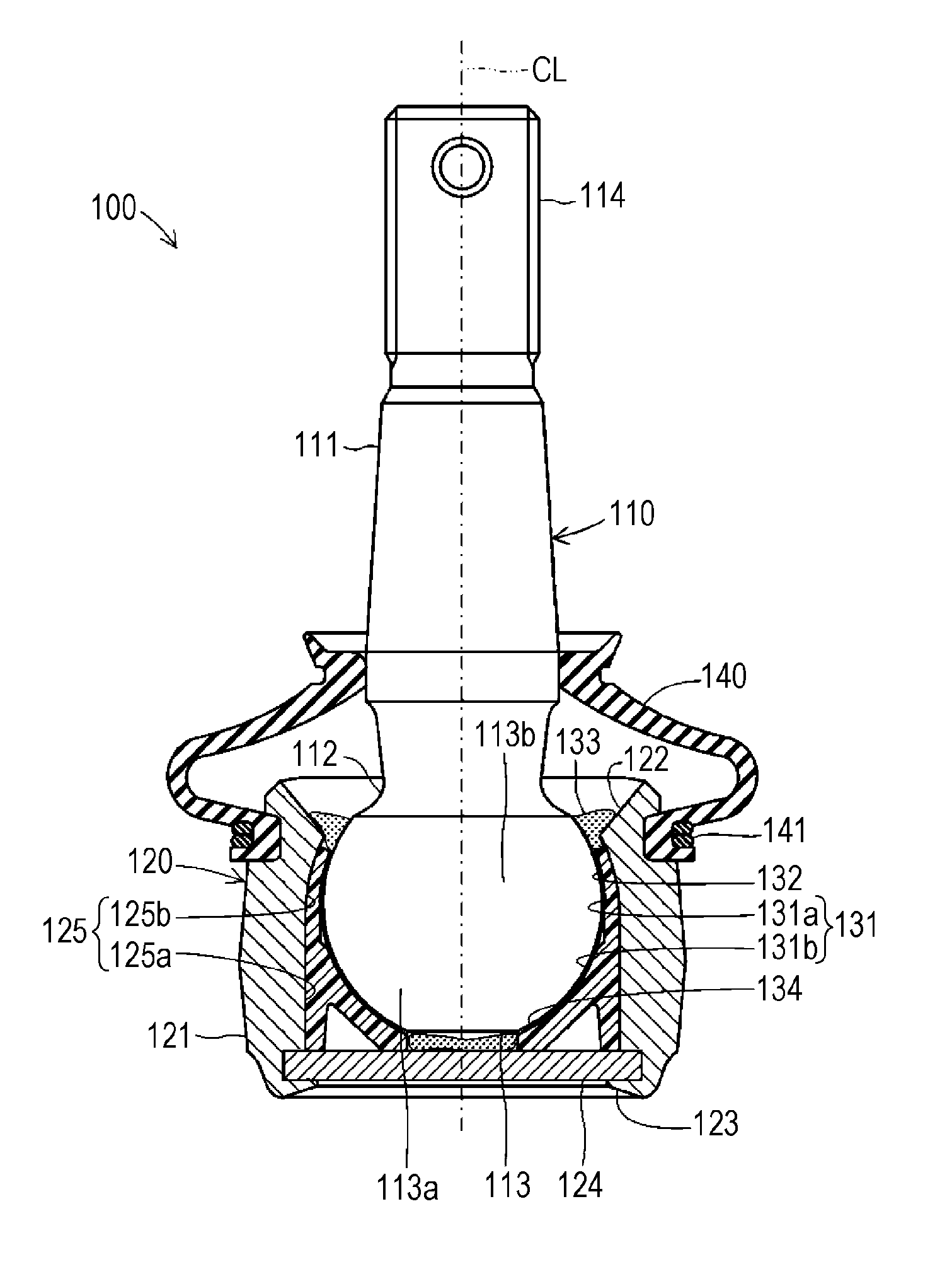
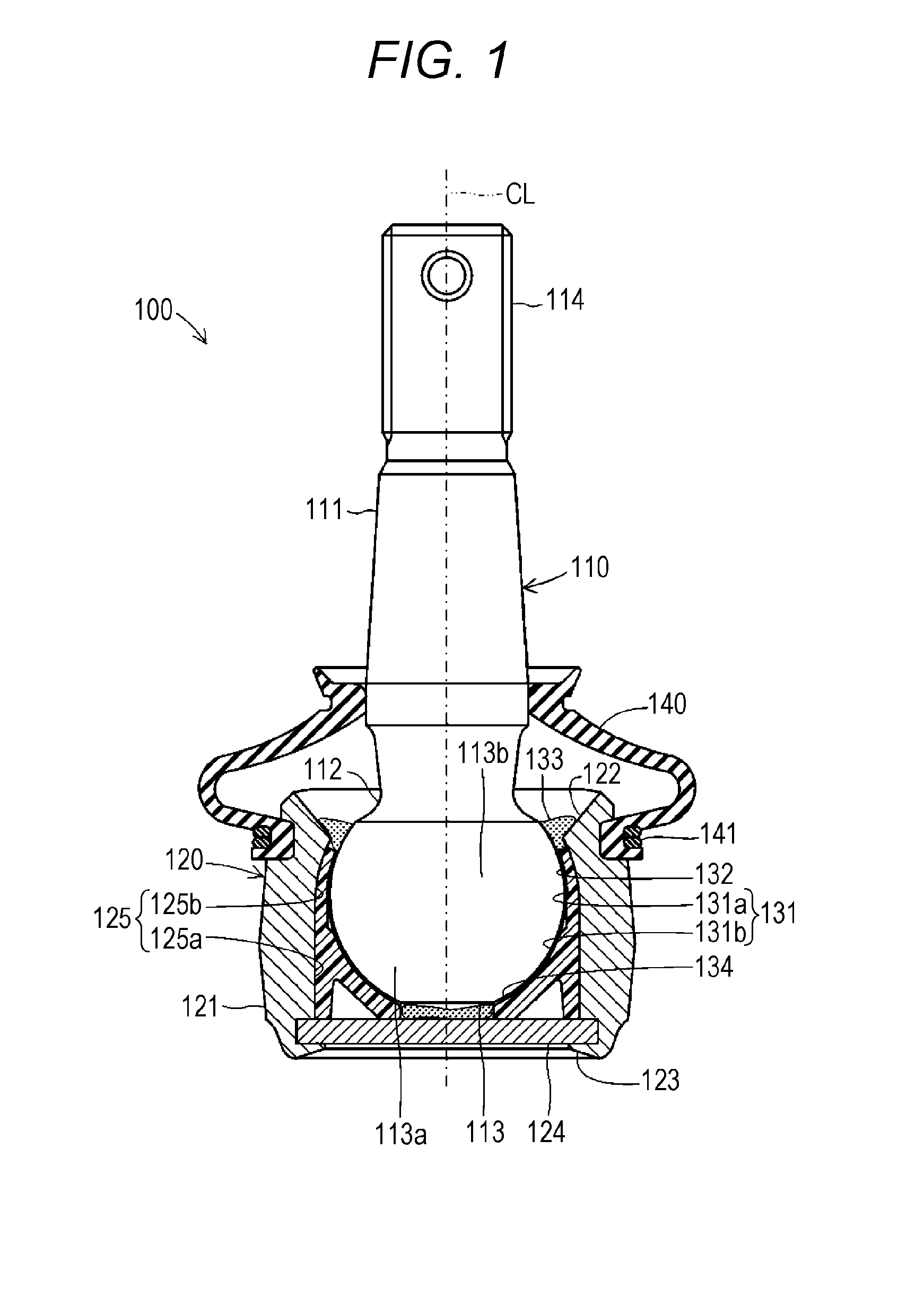
[0027]One embodiment of a ball seat according to the present invention will be described below with reference to the drawings. FIG. 1 is a vertical cross-sectional view schematically illustrating a structure of a ball joint 100 including a ball seat 130 according to the present invention. Note that, in each drawing referenced in this specification, some components are schematically illustrated by exaggeration for example, to help understanding of the present invention. Therefore, the size and the ratio of each component may be different. The ball joint 100 is a joint member for connecting components while allowing angle changes between the components in a suspension mechanism (suspension device) or steering mechanism (steering device) used for a vehicle such as an automobile.

[0028]The ball joint 100 mainly includes a ball stud 110, a socket 120, the ball seat 130, and a dust cover 140. Among these components, the ball stud 110 is made of steel. The ball stud 110 includes a substanti...


PUM


Abstract

A ball joint includes a ball seat for slidably holding a ball part of a ball stud. In the ball seat, a stud-side holder is housed in a housing of a socket while the stud-side holder is tilted and deformed to the ball part side by a tapered part. A first groove is formed in the stud-side holder of a holder of the ball seat. The first groove has an only shape with the curvature of the inner surface of the cross-section being a finite value, in other words, has a shape in which a shape with the curvature of the inner surface being an infinite value is not included. The first groove has a shape in which the first derivation value of the distance between the central axis of the tubular holder and the inner surface of the first groove consecutively changes.

Description

CROSS REFERENCE TO RELATED APPLICATIONS[0001]This application is a national stage application (under 35 U.S.C. §371) of PCT / JP2014 / 076686, filed Oct. 6, 2014, which claims benefit of Japanese application 2013-216048, filed Oct. 17, 2013, the contents of which are incorporated herein by reference in their entireties.TECHNICAL FIELD[0002]The present invention relates to a ball seat for slidably holding a spherical ball part formed at a tip of a shaft-shaped stud and a ball joint including the ball seat.BACKGROUND ART[0003]In a suspension mechanism (suspension device) and a steering mechanism (steering device) of a vehicle such as an automobile, a ball joint has been used for connecting shaft-shaped components so that these components can freely move. Normally, in a ball joint, a substantially spherical ball part formed at a tip of a shaft-shaped stud is housed in a tubular socket with base via a ball seat (also referred to as “bearing seat”) for slidably holding the ball part.[0004]In...

Claims


Application Information

Patent Timeline
Patent Type & Authority Applications(United States)
IPC IPC(8): F16C11/06
CPCF16C11/068F16C2326/05F16C2326/24F16C11/0623F16C11/0638F16C11/0685
Inventor ICHIKAWA, HISASHIITO, HIROAKI
Owner SOMIC ISHIKAWA INC
Why Eureka
Try Eureka