Riflescope with integrated wind sensor and targeting display

a technology of wind sensor and riflescope, which is applied in the direction of optical radiation measurement, instruments, image enhancement, etc., can solve the problems of time-consuming, difficult to implement bore-sighting techniques, and traditionally difficult to gather wind information, etc., and achieves the effect of simple and cost-effectiveness

Inactive Publication Date: 2016-09-15
CUBIC CORPORATION
View PDF11 Cites 29 Cited by
  • Summary
  • Abstract
  • Description
  • Claims
  • Application Information

AI Technical Summary

Benefits of technology

[0022]Techniques are disclosed for providing the weapon-mounted optical scope that provides for wind sensing and the display a ballistic solution without the need for a separate device. Embodiments may include various additional sensors housed within the weapon-mounted optical scope to provide data for the ballistic solution calculation. Embodiments may further include a display at the input aperture rather than internally at the first-focal-plane, enabling for simpler, more cost effective embodiments. Additionally or alternatively, embodiments may include a laser, separate from the wind sensing laser, to perform range-finding functions, and / or an enhanced-image assembly.

Problems solved by technology

However, gathering information regarding wind traditionally has been difficult.
Such technologies, however, can include components that are very expensive, may suffer from misalignment due to shock from the firing of a weapon, may implement bore-sighting techniques can be difficult and time consuming, and / or suffer from other issues.

Method used


Image

  • Riflescope with integrated wind sensor and targeting display
  • Riflescope with integrated wind sensor and targeting display
  • Riflescope with integrated wind sensor and targeting display

Examples


Embodiment Construction

[0052]The ensuing description provides embodiments only, and is not intended to limit the scope, applicability or configuration of the disclosure. Rather, the ensuing description of the embodiments will provide those skilled in the art with an enabling description for implementing an embodiment. It is understood that various changes may be made in the function and arrangement of elements without departing from the scope.

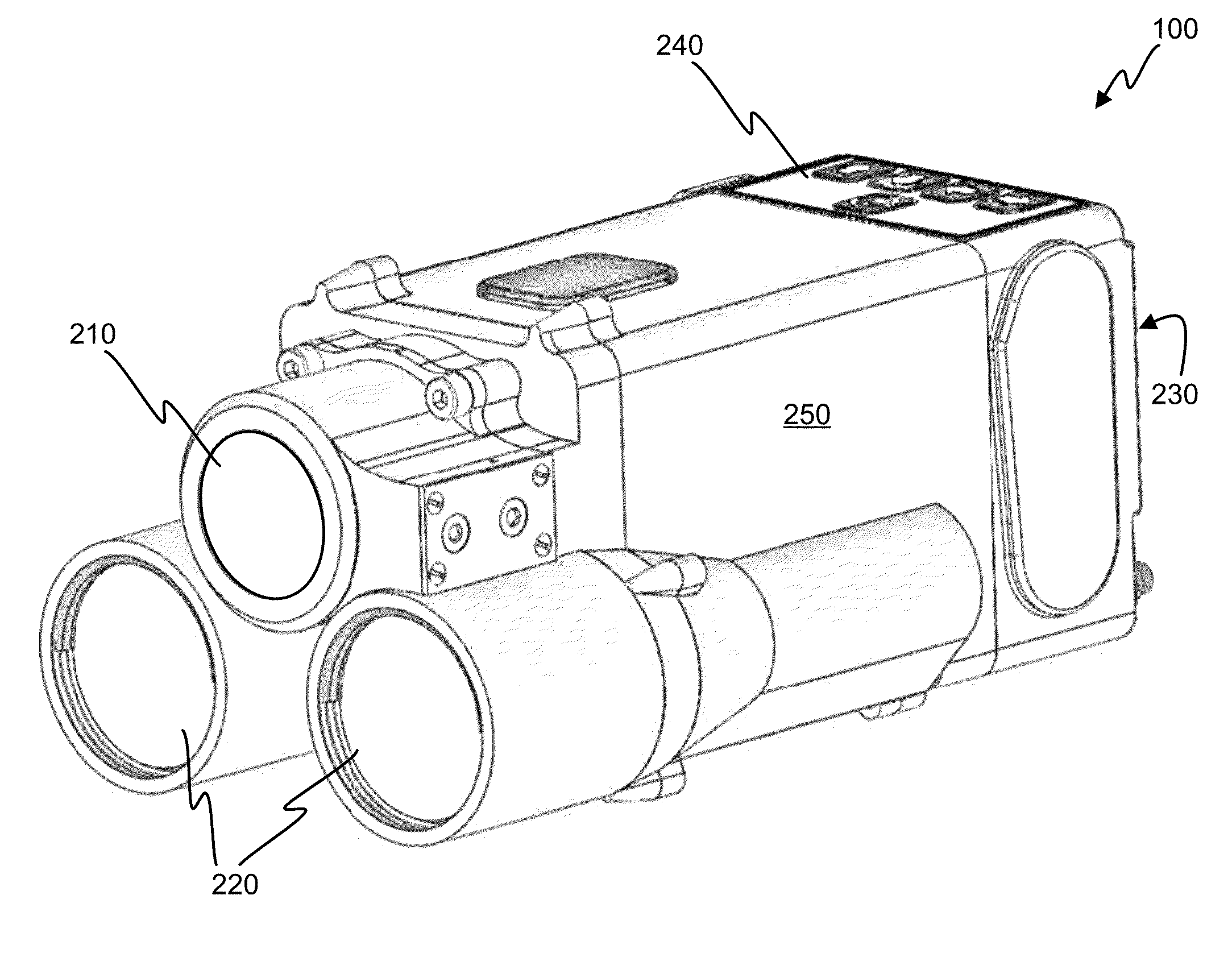
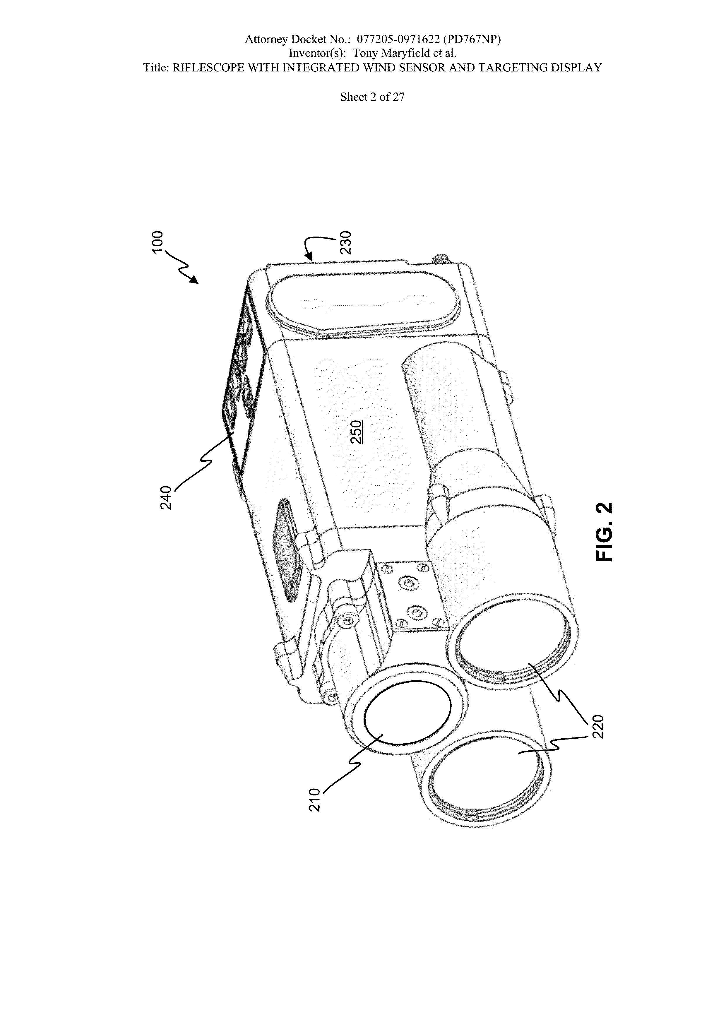
[0053]As provided herein, and broadly speaking, “bore sighting” a laser-based optical device to an apparatus means adjusting the laser-based optical device such that a laser of the laser-based optical device illuminates a target at which the apparatus is aimed. This ensures that range, wind, and / or other measurements taken by the laser-based devices accurately reflect measurements taken with respect to the target. A weapon-mounted laser-based rangefinder, for example, would not provide accurate range measurements of a target at which the weapon is pointed if the aim ...


PUM


Abstract

Techniques are disclosed for providing the weapon-mounted optical scope that provides for wind sensing and the display a ballistic solution without the need for a separate device. Embodiments may include various additional sensors housed within the weapon-mounted optical scope to provide data for the ballistic solution calculation. Embodiments may further include a display at the input aperture rather than internally at the first-focal-plane, enabling for simpler, more cost effective embodiments. Additionally or alternatively, embodiments may include a laser, separate from the wind sensing laser, to perform range-finding functions, and/or an enhanced-image assembly.

Description

CROSS-REFERENCES TO RELATED APPLICATIONS[0001]The present application claims benefit under 35 USC 119(e) of[0002]U.S. Provisional Application No. 62 / 130,349, filed on Mar. 9, 2015, entitled “Stabilized Laser Mounting Technique for Picatinny Rails,”[0003]U.S. Provisional Application No. 62 / 131,734, filed on Mar. 11, 2015, entitled “Sniper Multifunction Wind and Range Measurement with Ballistic Computer,”[0004]U.S. Provisional Application No. 62 / 137,094, filed on Mar. 25, 2015, entitled “Integrated Wind Laser Rangefinder Receiver,”[0005]U.S. Provisional Application No. 62 / 137,097, filed on Mar. 23, 2015, entitled “Infrared Laser Spot Finding,”[0006]U.S. Provisional Application No. 62 / 137,100, filed on Mar. 23, 2015, entitled “Integrated Wind Laser Rangefinder Receiver ASIC (Application Specific Integrated Circuit),”[0007]U.S. Provisional Application No. 62 / 137,111, filed on Mar. 23, 2015, entitled “Infrared Laser Bore-Sighting Using Infrared And CMOS Cameras,”[0008]U.S. Provisional Ap...

Claims


Application Information

Patent Timeline
Patent Type & Authority Applications(United States)
IPC IPC(8): F41G3/14F41G3/06F41G1/38F41G3/08H04N5/33G06T5/00G01S7/486G01S17/86
CPCF41G3/145H04N5/33F41G3/06F41G1/38F41G3/08G06T5/003G01S17/88G02B23/105G02B23/18G06T7/73H04N13/204Y02A90/10G06T7/33G01S17/86H04N23/64G02B27/20G06T2207/10016G06T2207/30212G06T5/20G06T5/50G06T11/60G06T2207/10012G06T2207/10048G06T2207/20224G06T7/20G01J1/44G01J2001/4406G01J2001/446G01S7/486H01L31/02005H01L31/02019H01L31/0203H01L31/03046H01L31/105F41G1/36F41G3/065G01P5/26G01S7/4816G01S17/95G02B13/14
Inventor MARYFIELD, TONYDADKHAH, MAHYARCUGNETTI, CHRISTIAN
Owner CUBIC CORPORATION
Why Eureka
Try Eureka