System and method of manufacturing composite modules

a composite module and manufacturing method technology, applied in the field of system and a manufacturing method of fibre reinforced composite modules, can solve the problems of excessive production time and production bottle-necks, high cost, and high tooling requirements, and achieve the effect of faster and/or more automated production procedures

Active Publication Date: 2017-06-20
AIRBUS OPERATIONS GMBH
View PDF8 Cites 0 Cited by
  • Summary
  • Abstract
  • Description
  • Claims
  • Application Information

AI Technical Summary

Benefits of technology

[0005]It is therefore an idea of the present invention to provide a new and improved method and system for overcoming one or more of the problems discussed above. In particular, it would be useful to provide a new system and method of manufacturing modules from a fibre-reinforced composite material for an aircraft or spacecraft which may enable a faster and / or more automated production procedure.
[0017]It will be noted that the form cores that are typically used or employed in the system and method are block-like elements, and are preferably formed of metal. As such, an individual form core is typically quite heavy, with a mass in the range of 10 to 50 kg. A full complement of the form cores needed in larger aerodynamic modules, such as wing panel modules and tail panel modules, may be several hundred such that the mass to be borne by the placement station for all of the form cores together may be in excess of 10 tonnes. This mass becomes problematic in turning or inverting all of the assembled form cores for placement in the moulding tool. In particular, the structure required not only to support that weight, but also to rotate it over the dimensions of an aircraft wing through an angle of 180° to invert it accordingly are extreme. An aspect of the present invention, however, overcomes this difficulty through the development of the turning apparatus or turning station which has been devised for turning or inverting the individual groups of assembled form cores before they are introduced into and / or received in the placement station. In this way, the placement station itself can be constructed in a far simpler and more cost effective manner, which also means that the structure can be duplicated more readily to enable multiple production facilities to operate in parallel without prohibitive cost.
[0021]In an embodiment of the invention, the placement station is configured to move between an upper position, at which the assembled form cores are received from the turning station, and a lower position, at which the assembled form cores are placed or deposited into or onto the moulding tool. In this regard, the placement station may include a holder or carrier frame configured to receive and to hold or carry the assembled form cores. This holder or carrier frame is also typically configured to move substantially vertically between the upper position and the lower position. In this way, the placement station in the system of the invention need only move vertically, so that no excessive and unwanted loading is generated in a support structure of the placement station as a result of rotating the massive form core arrays. Rather, the support structure of the placement station may simply be comprised of pillar-like hoist members for vertically moving the form core arrays suspended from the carrier frame above the moulding tool.

Problems solved by technology

Although the concept of co-curing components to produce an integral fibre-reinforced composite module is not new, current manufacturing concepts, especially for large modules, require complex, expensive and very heavy tooling, which makes the duplication of production lines difficult and prohibitively expensive.
This, in turn, leads to excessive production times and production bottle-necks.

Method used


Image

  • System and method of manufacturing composite modules
  • System and method of manufacturing composite modules
  • System and method of manufacturing composite modules

Examples


Embodiment Construction

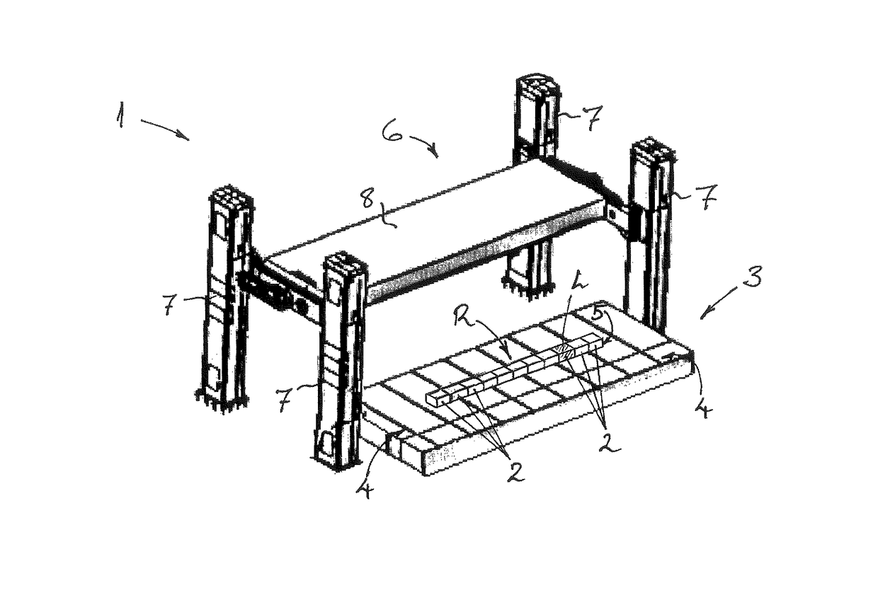
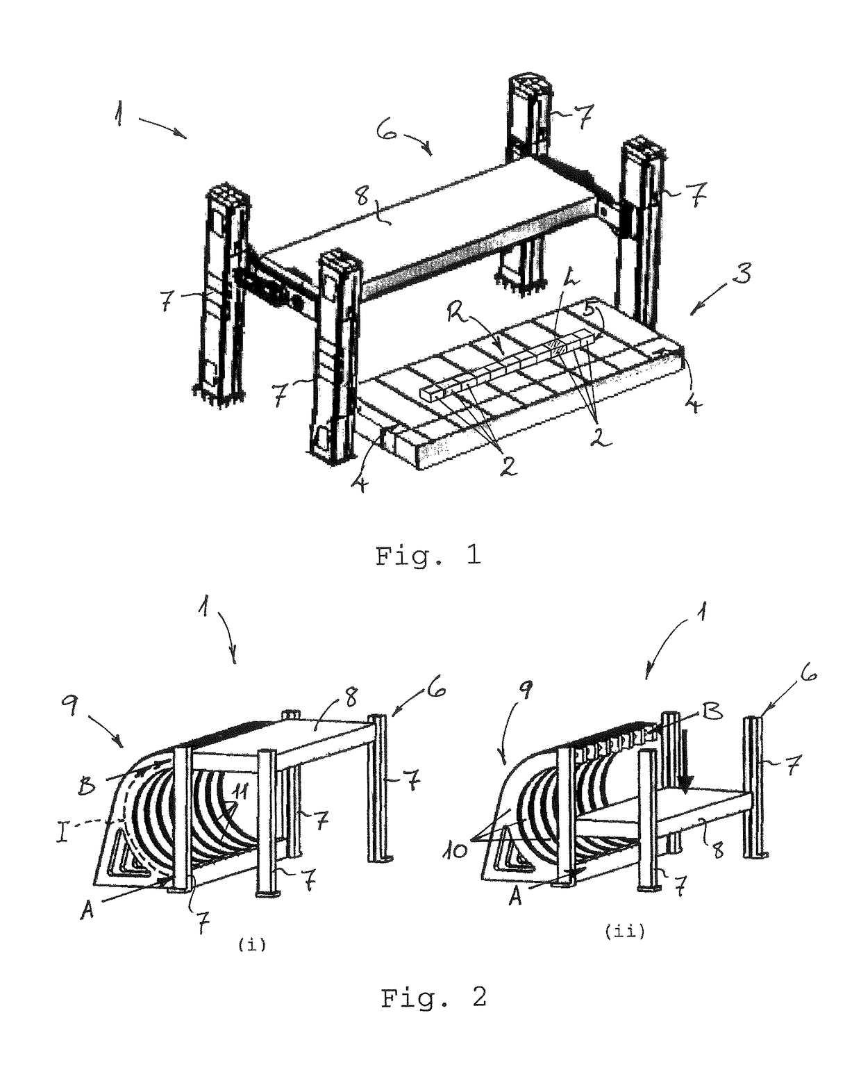
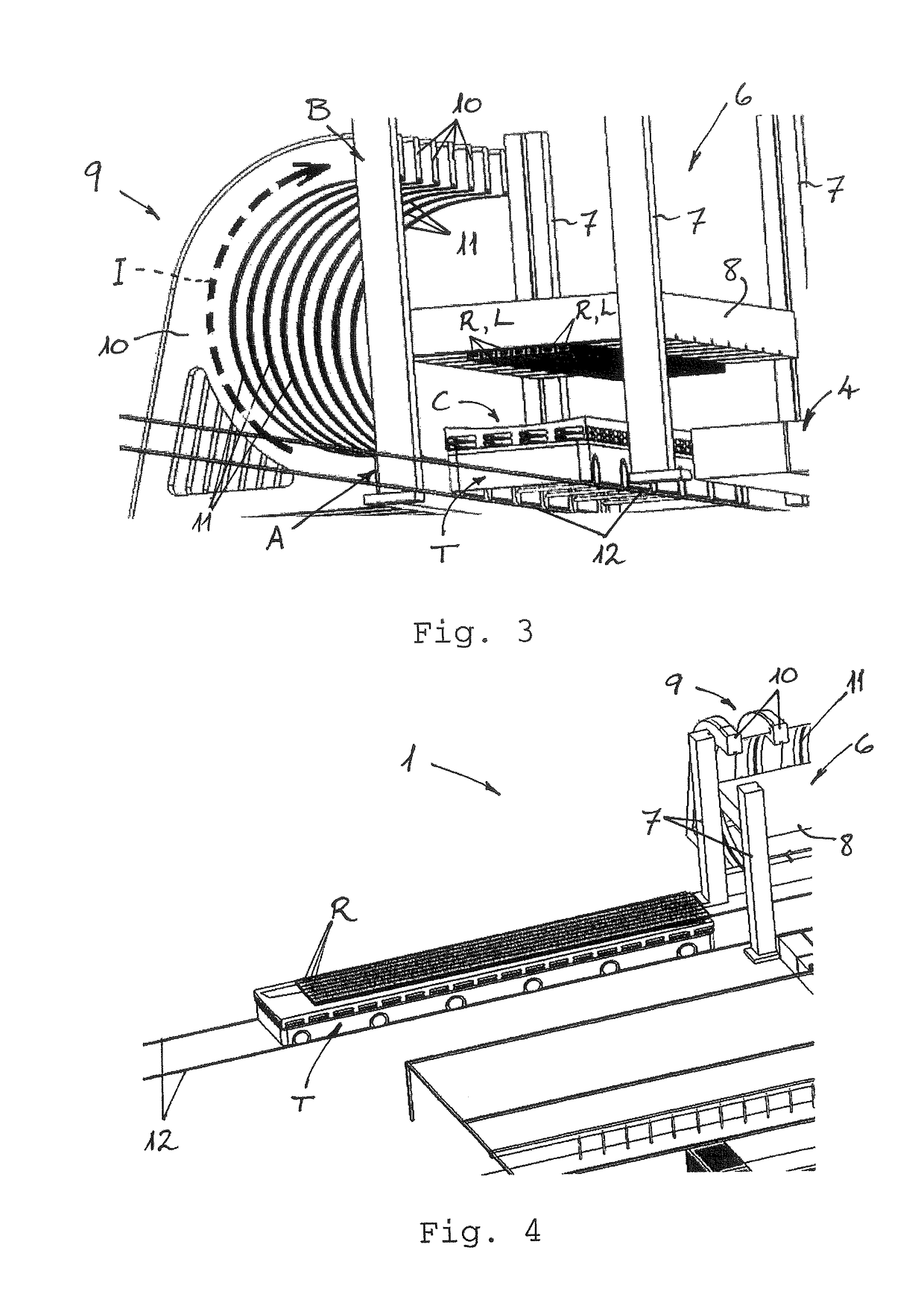
[0043]With reference to FIGS. 1 to 3 of the drawings, a system 1 for manufacturing a panel module P for an aircraft according to a preferred embodiment of the invention is illustrated schematically. The panel module P to be formed with this system 1 is comprised of a fibre-reinforced polymer, such as CFRP, and includes an integrated stiffening structure C with several elongate stiffening elements S, such as stringers, integrally formed on an inner side of an outer skin of the panel module P.

[0044]As will be understood by skilled persons, the panel skin or aerodynamic skin of the CFRP panel module takes its three-dimensional shape from an inner surface of a moulding tool T, which is laid-up with layers of reinforcing carbon fibers. These fibre layers may be dry fibre layers to be impregnated with resin in a resin transfer moulding (RTM) process, such as vacuum-assisted resin transfer moulding (VARTM), and then subsequently cured in an oven or autoclave, as is known in the art. Altern...


PUM

PropertyMeasurementUnit
massaaaaaaaaaa
massaaaaaaaaaa
massaaaaaaaaaa

Abstract

A system for producing a fiber-reinforced composite module, such as a panel module, having an integrated stiffening structure for an aircraft or spacecraft includes a form core assembly station for assembling a plurality of form cores covered with reinforcing fiber layers to constitute at least one stiffening element of the integrated stiffening structure, a form core placement station which receives assembled form cores from the assembly station for placing or depositing the assembled form cores in or on a molding tool, and a turning station for rotating or inverting the assembled form cores. The turning station is configured to convey or transport the assembled form cores from the assembly station to the placement station. The turning station defines a path which is configured to rotate or invert the assembled form cores as they are conveyed or moved to the placement station.

Description

FIELD OF THE INVENTION[0001]The present invention relates to a system and a method of manufacturing a fibre-reinforced composite module, such as a panel module, having an integrated stiffening structure, and especially for use in an aircraft or spacecraft.[0002]Thus, the systems and methods described herein are particularly suitable for use in the fabrication of airframe components or modules of aircraft or spacecraft, especially wing and tail-plane modules or structures, and it will be convenient to describe the invention herein in this exemplary context. It will be understood, however, that the described systems and methods are not limited to this application, but may be employed to manufacture body structures for various other vehicles, such as trains, automobiles, trucks, or ships. These systems and methods are therefore suitable for a range of nautical, aeronautical, automotive, and aerospace applications.[0003]The inventors have developed a modular manufacturing system and met...

Claims


Application Information

Patent Timeline
Patent Type & Authority Patents(United States)
IPC IPC(8): B65G7/08B29D99/00
CPCB29D99/0014
Inventor ENGELS, ALEXANDERZAHLEN, PIERREMEYER, LARS
Owner AIRBUS OPERATIONS GMBH
Why Eureka
Try Eureka