Method and system for fabricating a module

a technology of module and method, applied in the direction of furnaces, heat treatment equipment, soldering equipment, etc., can solve the problems of increasing workload and lead time of the overall manufacturing process, stringer welding to skin panels often generating distortions,

Inactive Publication Date: 2015-04-02
AIRBUS OPERATIONS GMBH
View PDF12 Cites 9 Cited by
  • Summary
  • Abstract
  • Description
  • Claims
  • Application Information

AI Technical Summary

Benefits of technology

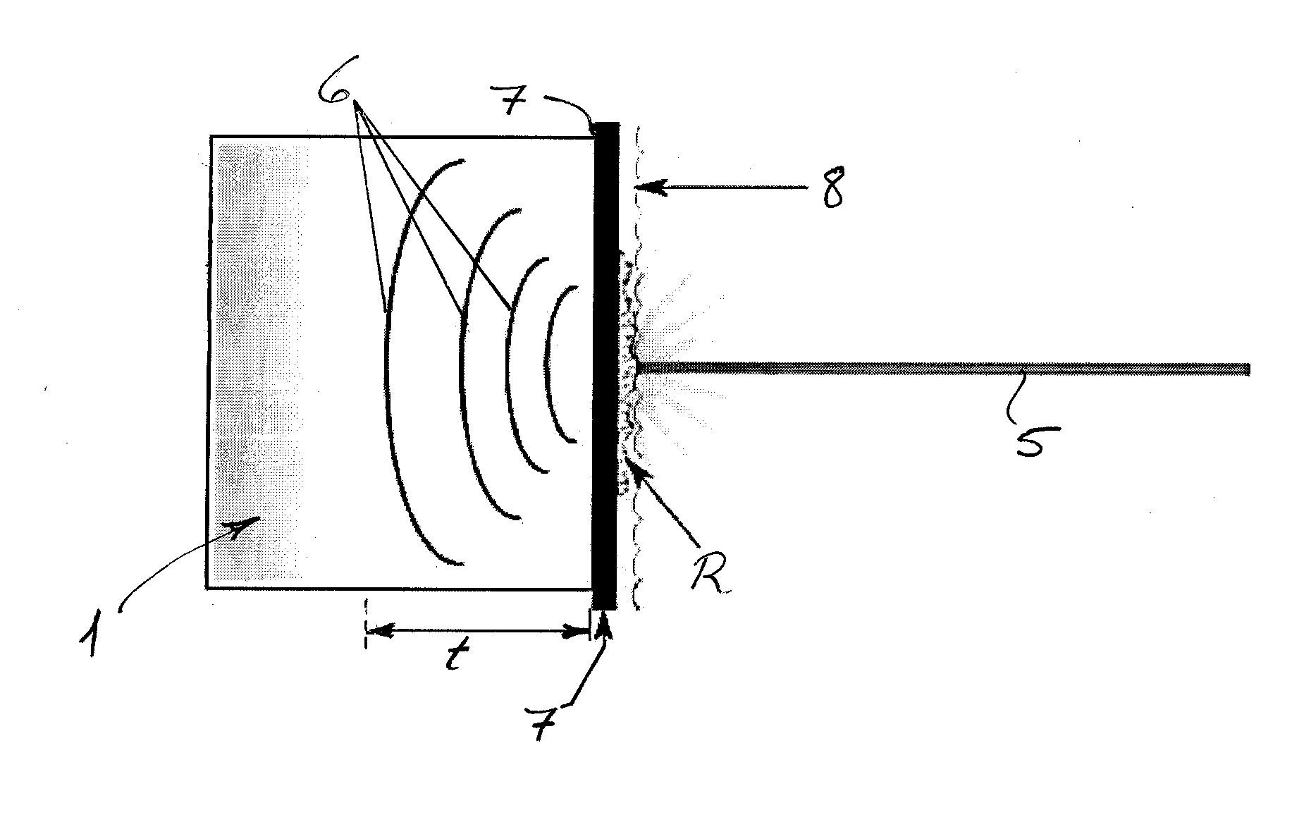
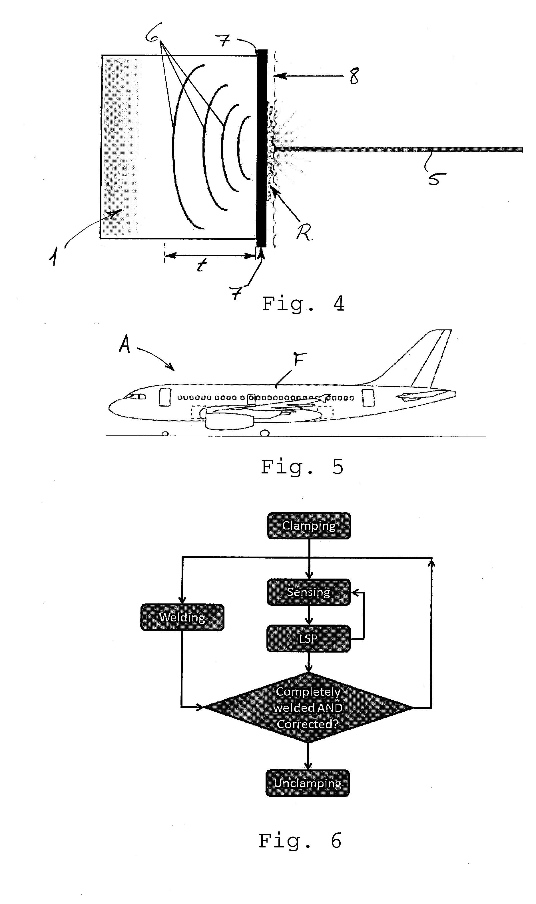
[0021]According to a further aspect, the present invention provides a method of fabricating a module for an airframe or fuselage structure of an aircraft or spacecraft, including the steps of positioning a first member adjacent to a second member at a work station or assembly station, welding the first member to the second member at the work station or assembly station to produce the module having a welded joint between the first and second members, and treating the first member, the second member, and / or the welded joint at the work station or assembly station to compensate for, or correct, distortion in the module caused by the welding. The method further provides generating residual compressive stresses in a surface region of the module, and generating a shock wave in a region of at least one of the first member, the second member, and the welded joint.

Problems solved by technology

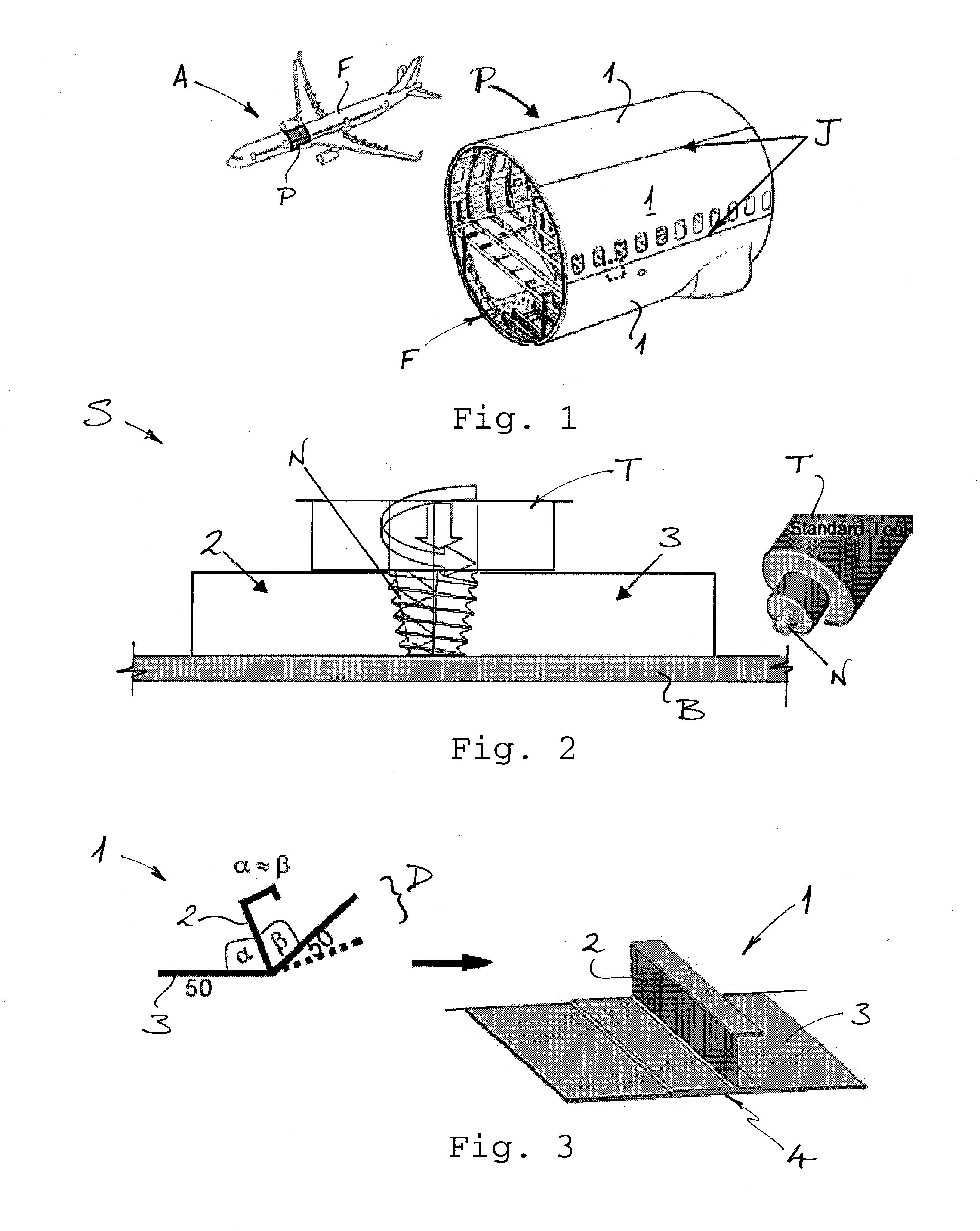
With current manufacturing techniques, however, the welding of stringers to skin panels often generates distortions (sometimes called the “Zeppelin effect”) which need to be corrected in separate manufacturing procedures.
In other words, the welded and stiffened panels need to be transferred or transported to other processing stations for further treatment and this in turn significantly increases the workload and the lead times for the overall manufacturing process of integrally stiffened panel modules in aircraft manufacture.

Method used


Image

  • Method and system for fabricating a module
  • Method and system for fabricating a module
  • Method and system for fabricating a module

Examples


Embodiment Construction

[0031]The accompanying drawings are included to provide a further understanding of the present invention and are incorporated in and constitute a part of this specification. The drawings illustrate particular embodiments of the invention and together with the description serve to explain the principles of the invention. Other embodiments of the invention and many of the attendant advantages of the invention will be readily appreciated as they become better understood with reference to the following detailed description.

[0032]It will be appreciated that common and / or well understood elements that may be useful or necessary in a commercially feasible embodiment are not necessarily depicted in order to facilitate a more abstracted view of the embodiments. The elements of the drawings are not necessarily illustrated to scale relative to each other. It will further be appreciated that certain actions and / or steps in an embodiment of a method may be described or depicted in a particular o...


PUM

PropertyMeasurementUnit
depthaaaaaaaaaa
residual compressive stressesaaaaaaaaaa
dynamic yield strengthaaaaaaaaaa

Abstract

A method of fabricating a module for an airframe or fuselage structure of an aircraft or spacecraft includes positioning a first member adjacent to a second member at an assembly station; welding the first member to the second member at the assembly station to produce a module having a welded joint between the first and second members; and peening at least one of the first member, the second member, and the welded joint at the assembly station to compensate for or to correct distortion caused by the welding.

Description

CROSS-REFERENCE TO RELATED APPLICATION[0001]This application claims the benefit of the European Patent Application No. 13186578.4 filed on Sep 30, 2013, the entire disclosures of which are incorporated herein by way of reference.BACKGROUND OF THE INVENTION[0002]The present invention relates to a method and a system for fabricating a module, such as a stiffened panel, for an airframe or fuselage structure of an aircraft or spacecraft. The module fabricated according to the method and system of the invention comprises parts or members, typically of metal or a metal alloy, which are or may be welded together.[0003]The method and system of the invention are especially suitable for use in fabrication of an airframe or fuselage structure of an aircraft or spacecraft, and it is convenient to describe the invention herein in this exemplary context. It will be appreciated, however, that the method and system of the invention are not limited to this application, but may be used to provide mod...

Claims


Application Information

Patent Timeline
Patent Type & Authority Applications(United States)
IPC IPC(8): B23K31/00B23K26/24B23K31/12B23K26/00B23K20/12B23K31/02
CPCB23K31/003B23K20/12B23K31/02B23K2201/006B23K26/0069B23K26/24B23K31/12B23K20/122B23K26/28B23K31/00C21D10/005B24C1/10B23K26/32C21D9/50B23K2101/18B23K2103/10B23K26/356B23K2101/006
Inventor FURFARI, DOMENICOPACCHIONE, MARCORICHTER-TRUMMER, VALENTIN
Owner AIRBUS OPERATIONS GMBH
Why Eureka
Try Eureka