Mutual authentication of software layers

Active Publication Date: 2016-09-15
VISA INT SERVICE ASSOC
View PDF2 Cites 38 Cited by
  • Summary
  • Abstract
  • Description
  • Claims
  • Application Information

AI Technical Summary

Problems solved by technology

Because of the modularized nature of such an environment, a security vuln

Method used


Image

  • Mutual authentication of software layers
  • Mutual authentication of software layers
  • Mutual authentication of software layers

Examples


example implementation

III. Example Implementation of Binding Algorithm

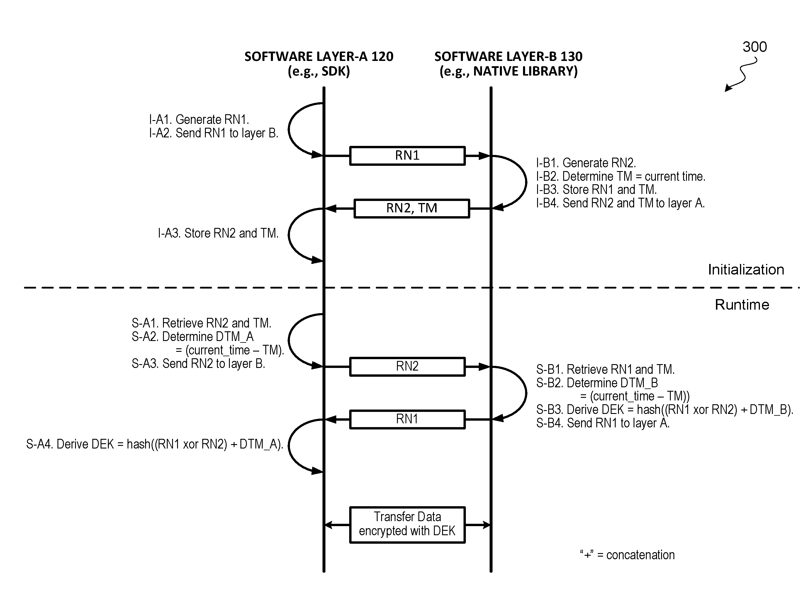
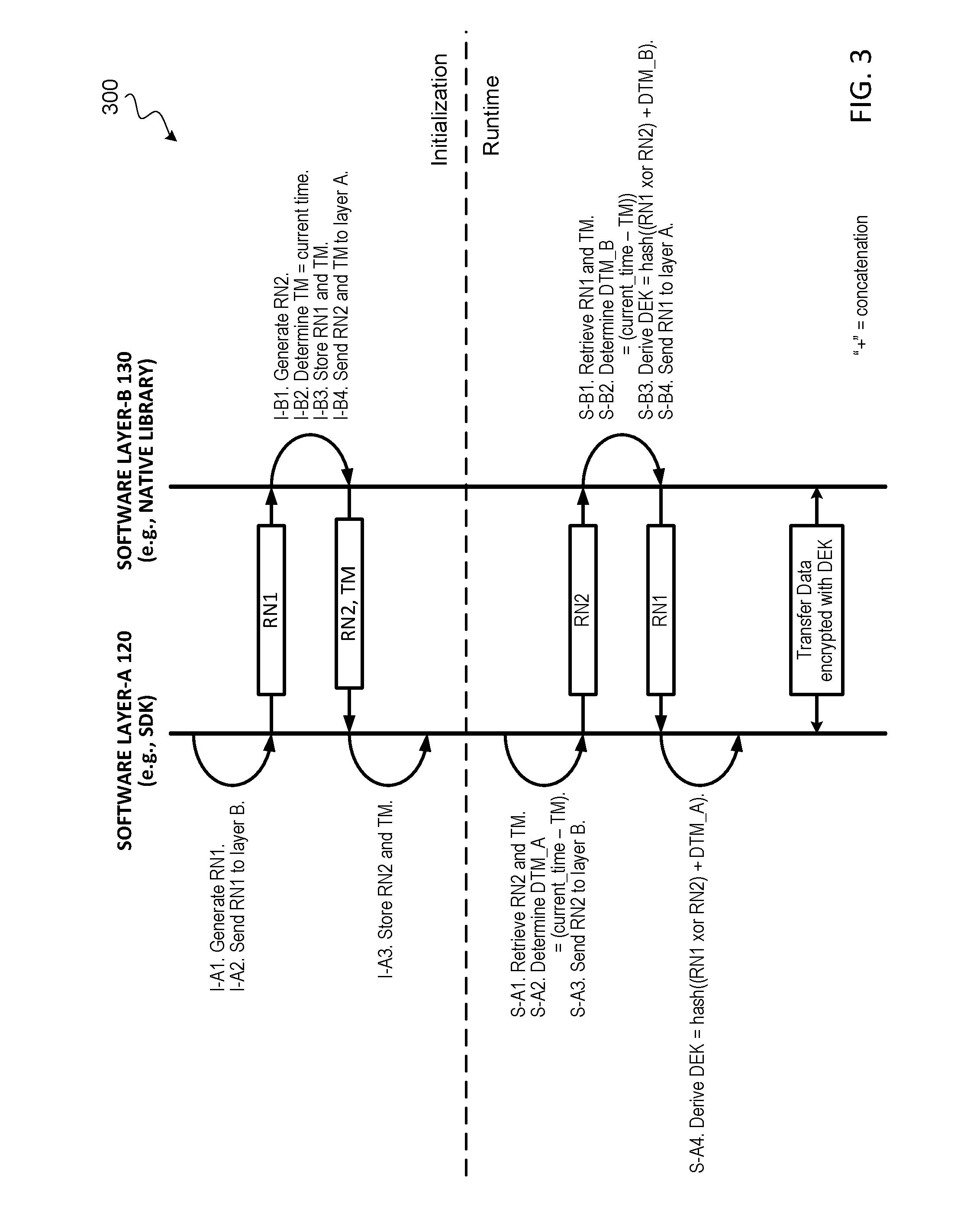
[0072]FIG. 8 illustrates a communication flow diagram of an example implementation of a binding algorithm to bind a first software layer (e.g., software layer-A 120) to a second software layer (e.g., software layer-B 130) during the first time initialization of a software application, according to some embodiments. In some embodiments, software layer-A 120 can be a SDK (e.g., written in Java), and software layer-B can be a native library (e.g., written in C or C++), or vice versa. In some embodiments, the two software layers can be written in the same language. For ease of explanation, the steps performed in the binding algorithm during the first time initialization are denoted as “I-Xn” where X indicates the software layer, and n is the step performed by that software layer. Various encryption keys (referred to as binding keys) are derived and used in the binding algorithm. The binding keys used in the binding algorithm are denoted as...


PUM


Abstract

Techniques for establishing mutual authentication of software layers of an application are described. During initialization of the application, the software layers execute a binding algorithm to exchange secrets to bind the software layers to one another. During subsequent runtime of the software application, the software layers execute a runtime key derivation algorithm to combine the secrets shared during initialization with dynamic time information to generate a data encryption key. The software layers can then securely transfer data with each other by encrypting and decrypting data exchanged between the software layers using the dynamically generated data encryption key.

Description

CROSS-REFERENCES TO RELATED APPLICATIONS[0001]This application claims the benefit of priority to U.S. Provisional Application No. 62 / 132,289 filed on Mar. 12, 2015, which is herein incorporated by reference in its entirety for all purposes.BACKGROUND[0002]A software application may have multiple software components or software layers (may also be referred to as software libraries) that communicate or exchange data with each other. For example, code executing in one layer may call functions implemented in another layer, or code executing in one layer may pass parameters or data to another layer. Because of the modularized nature of such an environment, a security vulnerability can exist at the exposed interface between the software layers. For instance, a man-in-the-middle application can eavesdrop on the data being passed between the software layers to obtain sensitive information, or unauthorized code can directly invoke functions implemented in a shared software layer and obtain s...

Claims


Application Information

Patent Timeline
IPC IPC(8): G06F21/60G06F21/44
CPCG06F21/445G06F21/602G06F21/14G06F21/577H04L9/0869G06F21/12G06F2211/003H04L9/0861H04L9/0877H04L9/0897H04L9/3234H04L9/3271H04L9/3273H04L2209/127G06F21/606
Inventor MANSOUR, RASTABHATTACHARYA, SOUMENDRAYOUDALE, ROBERT
Owner VISA INT SERVICE ASSOC
Why Eureka
Try Eureka