Trigger activated tools having activation lockouts

a technology of activation lockout and trigger, which is applied in the direction of manufacturing tools, portable power-driven tools, electric devices, etc., can solve the problem of inadvertent movement of the trigger from the normal position

Active Publication Date: 2016-09-15
HUBBELL INC
View PDF7 Cites 14 Cited by
  • Summary
  • Abstract
  • Description
  • Claims
  • Application Information

AI Technical Summary

Benefits of technology

[0008]Trigger activated tools are provided that include activation lockouts, which prevent inadvertent activation of the tools.

Problems solved by technology

Unfortunately, the use of such trigger activated tools often occurs under conditions that can lead to inadvertent movement of the trigger from the normal position to the activation position.

Method used


Image

  • Trigger activated tools having activation lockouts
  • Trigger activated tools having activation lockouts
  • Trigger activated tools having activation lockouts

Examples


Embodiment Construction

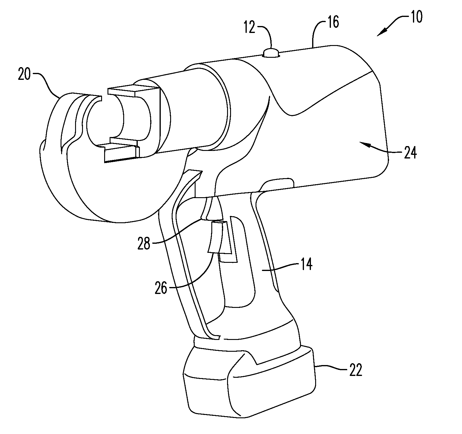
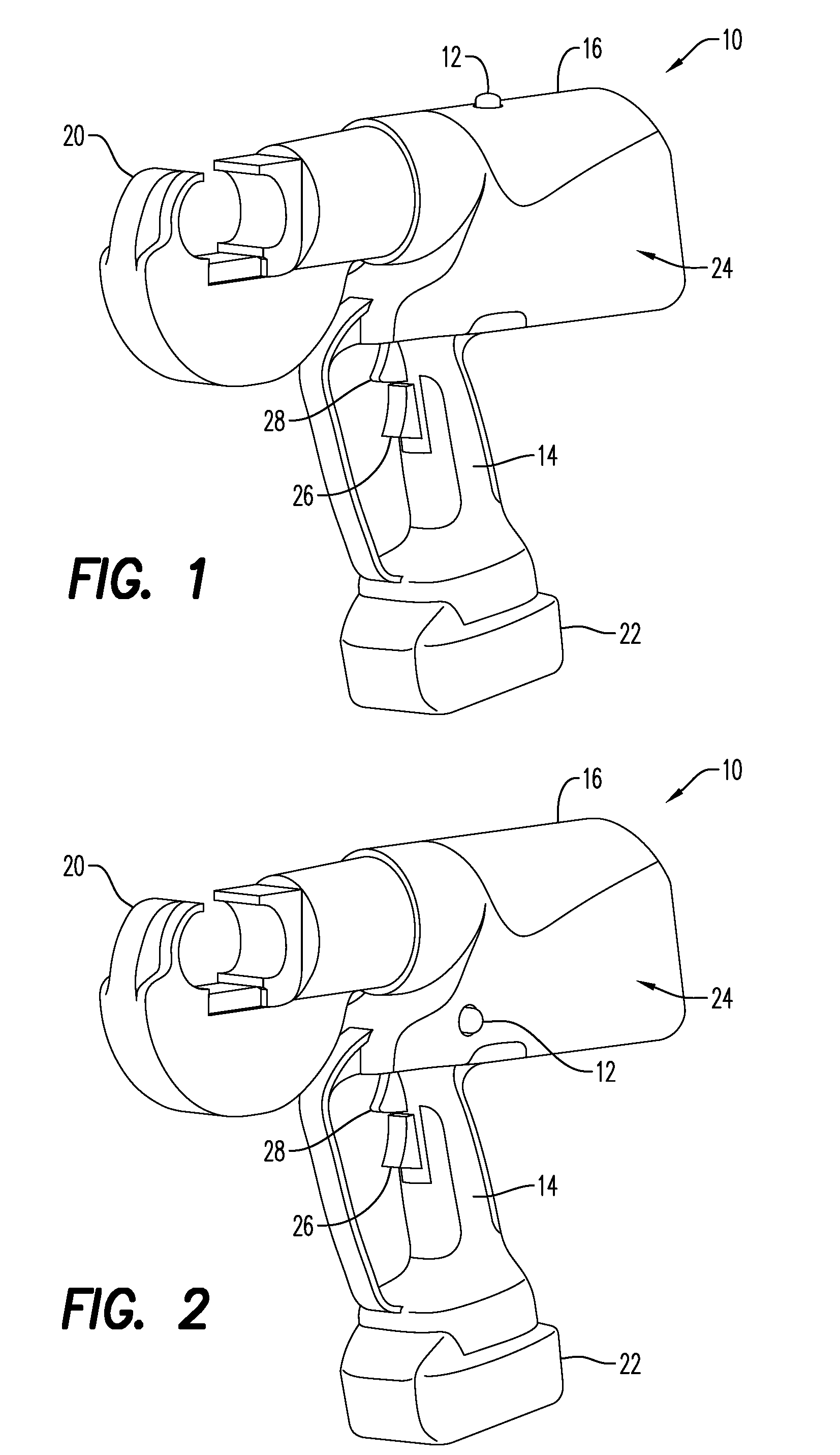
[0052]Referring to the drawings and in particular to FIGS. 1 and 2, exemplary embodiments of a pistol style trigger activated tool according to the present disclosure is shown and is generally referred to by reference numeral 10.

[0053]Advantageously, tool 10 includes an activation lockout 12, which prevent inadvertent activation of the tool. Here, activation lockout 12 is an electrical reset lockout that allows movement of the activation trigger from the normal position to the activation position, but prevents such movement from activating tool 10 unless the activation lockout has been pressed. In this manner, activation lockout 12—when in the form of the electrical reset lockout—prevents inadvertent activation of tool 10 by requiring both pressing of the lockout and activation of the trigger.

[0054]In the embodiment of FIG. 1, activation lockout 12 is positioned at on a handle portion of tool 10, illustrated as an upper wall 14. In this manner, the user can hold tool 10 with a first...


PUM


Abstract

Trigger activated tools are provided that have one or more activation lockouts. The activation lockouts include electrical resets, variable position lockouts, mechanical lockouts, shield lockouts, and any combinations thereof.

Description

CROSS REFERENCE TO RELATED APPLICATIONS[0001]This application claims the benefit of U.S. Provisional Application No. 62 / 131,596 filed Mar. 11, 2015 on the entire contents of which are incorporated by reference herein.BACKGROUND[0002]1. Field of the Disclosure[0003]The present disclosure is related to trigger activated tools. More particularly, the present disclosure is related to trigger activated tools having activation lockouts.[0004]2. Description of Related Art[0005]Trigger activated tools are commonly used in the industrial, energy, construction, telecommunications, petrochemical, data center, transportation and construction industries. Such tools can include, but are not limited to, C-Head crimping tools, jaw crimping tools, cutter tools and others.[0006]When activation of such tools is desired, the trigger is moved from a normal position to an activation position. Unfortunately, the use of such trigger activated tools often occurs under conditions that can lead to inadvertent...

Claims


Application Information

Patent Timeline
Patent Type & Authority Applications(United States)
IPC IPC(8): H01H3/20B26B15/00B25F5/00
CPCH01H3/20B26B15/00B25F5/00B25F5/02H01H9/06H01H9/24H01H21/20H01H21/24H01H2009/065
Inventor CHIASSON, MARK ANDREWFAUCHER, THOMAS ROMEOLEFAVOUR, JOHNPOIRIER, ROBERTWASON, PETER MATTHEW
Owner HUBBELL INC
Why Eureka
Try Eureka