Cooling system to reduce liquid metal embrittlement in metal tube and pipe

a cooling system and metal tube technology, applied in the field of systems and methods for the manufacture of heat exchangers, can solve the problems of inability to cool a brazing furnace fast enough, and other drawbacks of brazing furnaces

Inactive Publication Date: 2016-09-22
LUVATA ALLTOP ZHONGSHAN LTD
View PDF18 Cites 2 Cited by
  • Summary
  • Abstract
  • Description
  • Claims
  • Application Information

AI Technical Summary

Benefits of technology

This patent describes how to make a better way to cool down a brazed heat exchanger by putting it into a special chamber where we use pressure to change its shape and then move it out to have some parts added on. Once that's done, we put it back inside the chamber for another step called braizing - which means melting together certain parts with other materials like metal powder. Then we take it outside again and spray it with something really hot to help keep everything cool while it cools down. Overall, this process makes sure that the heat exchanger works even better because all those extra steps made it stronger and more efficient at transferring energy from one part to another.

Problems solved by technology

The technical problem addressed in this patent text relates to improving the cooling process after brazing in order to prevent issues like liquid metal embrittlement and over annealed joints when manufacturing heat exchangers. Current fan systems placed outside of the brazing furnace cannot quickly cool the heat exchanger sufficiently to avoid these challenges.

Method used


Image

  • Cooling system to reduce liquid metal embrittlement in metal tube and pipe
  • Cooling system to reduce liquid metal embrittlement in metal tube and pipe
  • Cooling system to reduce liquid metal embrittlement in metal tube and pipe

Examples


Embodiment Construction

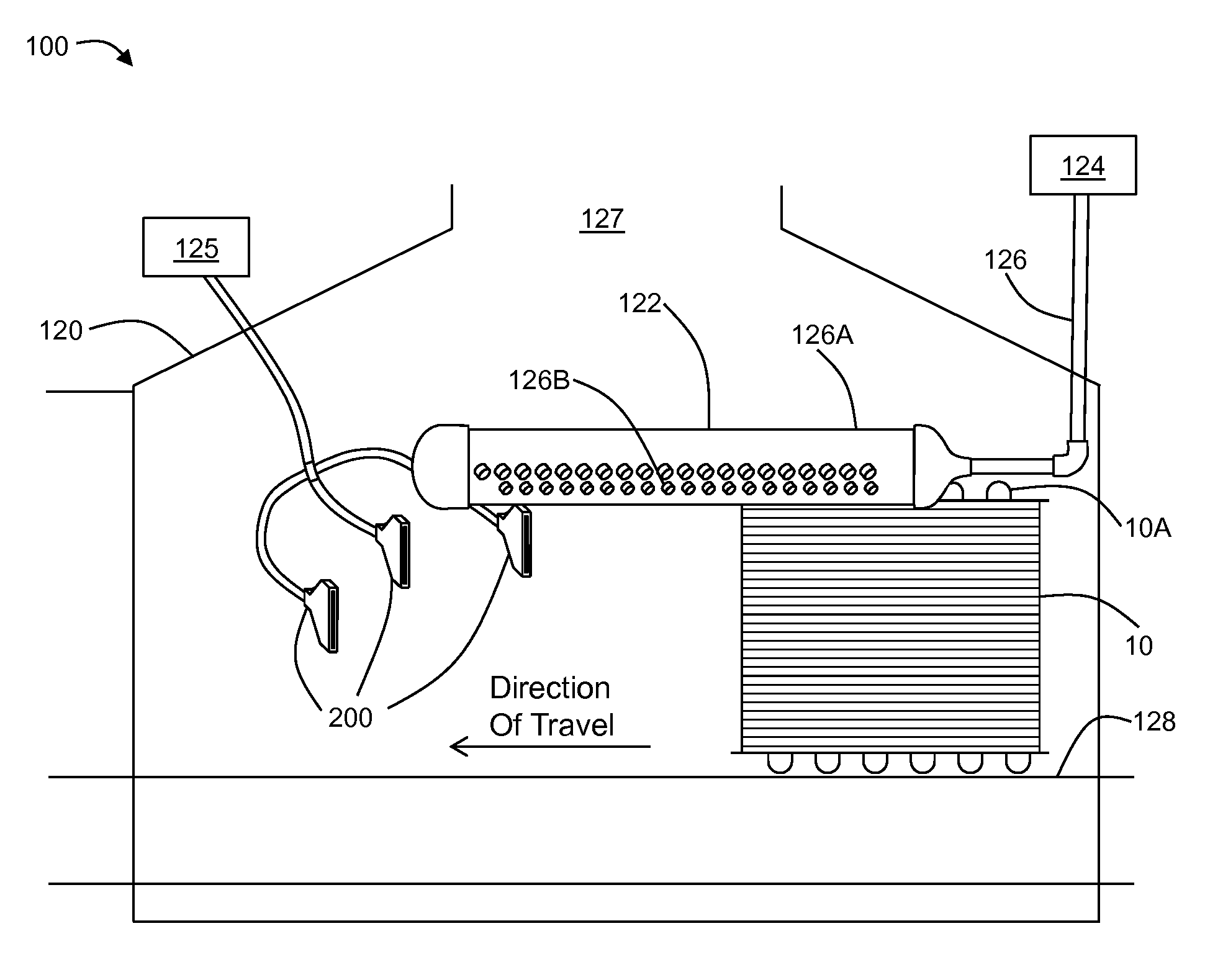
[0014]In one embodiment, a cooling system according to the present disclosure is configured to cool a brazed assembly that has been brazed in a brazing furnace. Brazing is a process for joining parts, often of dissimilar compositions, to each other. Typically, a brazing filler metal (“filler material”) having a melting point lower than that of the parts to be joined together is interposed between the parts that form an assembly. The filler material can be a brazing ring, brazing plate, clad, or the like. The assembly of the parts to be brazed and the filler metal is then heated to a temperature sufficient to melt the filler material but generally lower than the melting point of the parts. Upon cooling, a strong, void-free joint is formed.

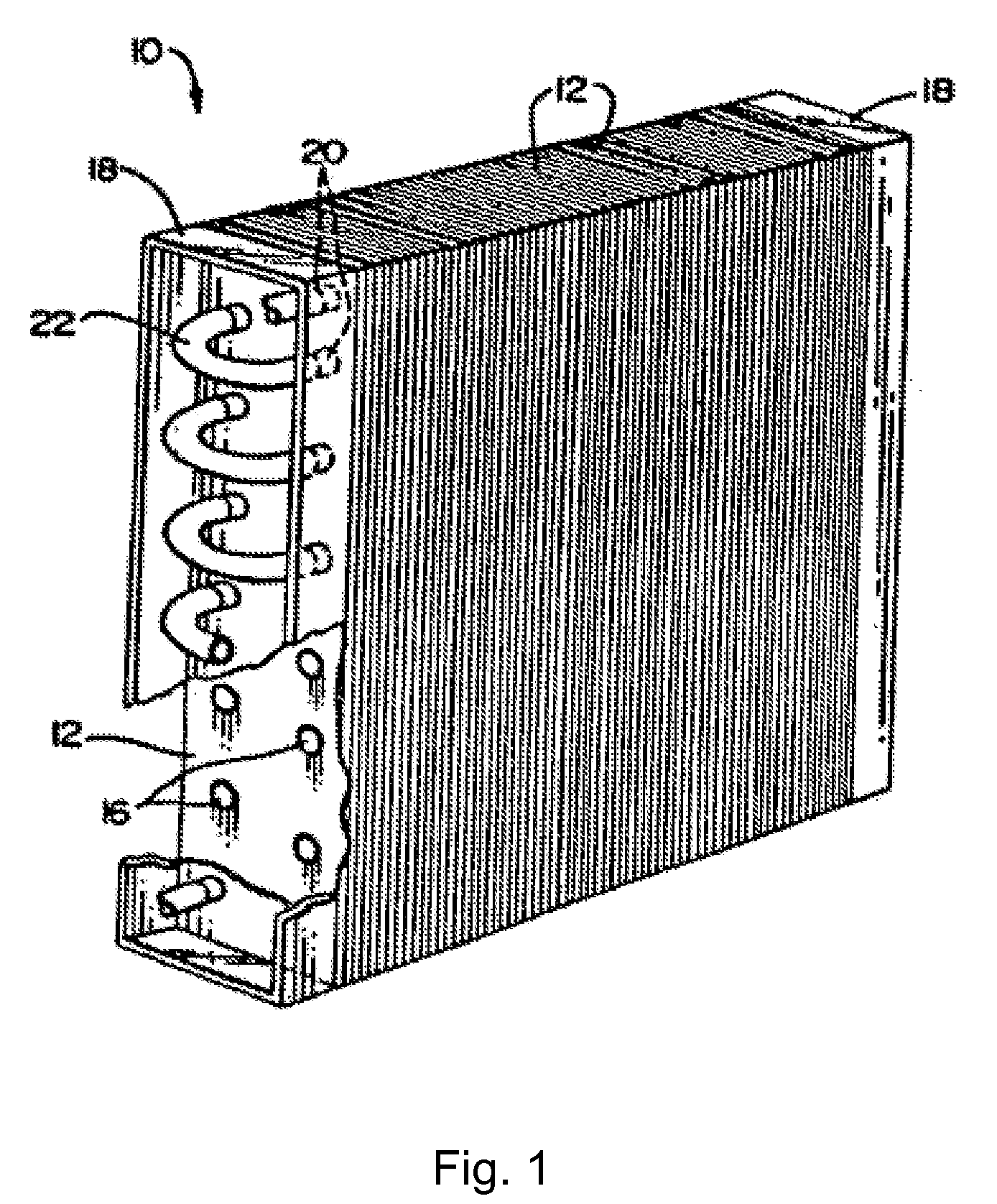
[0015]FIG. 1 depicts a plate fin and tube heat exchanger 10 containing plate fins 12 according to a known configuration. Each plate fin has a plurality of holes 16. A common method of manufacturing heat exchanger 10 is to arrange a plurality of plat...


PUM

PropertyMeasurementUnit
Flow rateaaaaaaaaaa
Distanceaaaaaaaaaa

Abstract

A system and method for cooling a heat exchanger.

Description


Claims


Application Information

Patent Timeline
Owner LUVATA ALLTOP ZHONGSHAN LTD
Why Eureka
Try Eureka