Liquid supply device and liquid ejection device

a liquid supply device and liquid ejection technology, applied in the direction of positive displacement liquid engines, fluid jet surgical cutters, machines/engines, etc., can solve the problems of labor and time required to perform plunger pump maintenance, and achieve the effect of simple maintenan

Active Publication Date: 2016-09-22
COLUMBIA PEAK VENTURES LLC
View PDF1 Cites 2 Cited by
  • Summary
  • Abstract
  • Description
  • Claims
  • Application Information

AI Technical Summary

Benefits of technology

[0006]An advantage of some aspects of the invention is that a variation in pressure of a liquid to be supplied is suppressed with a mechanism for which maintenance is simple in consideration of the technology of the related art.

Problems solved by technology

In the case of the technology of the foregoing related art, it takes some labor and time to perform maintenance of the plunger pumps.
In particular, when the plunger pumps are used for medical treatment, problems particularly occur in cases in which exchange or sterilization is necessary.

Method used


Image

  • Liquid supply device and liquid ejection device
  • Liquid supply device and liquid ejection device
  • Liquid supply device and liquid ejection device

Examples


Embodiment Construction

[0039]First, an ejection mechanism and a suction mechanism for a liquid will be described by describing an overall of a liquid ejection device 20 with reference to FIGS. 1 to 10.

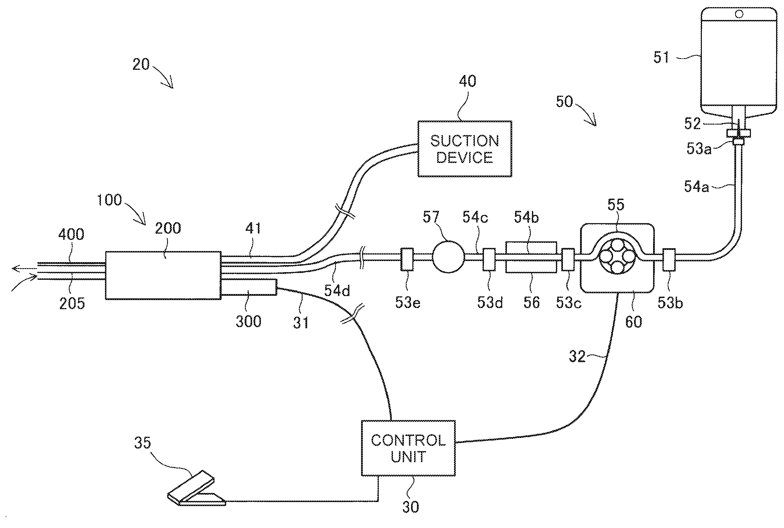
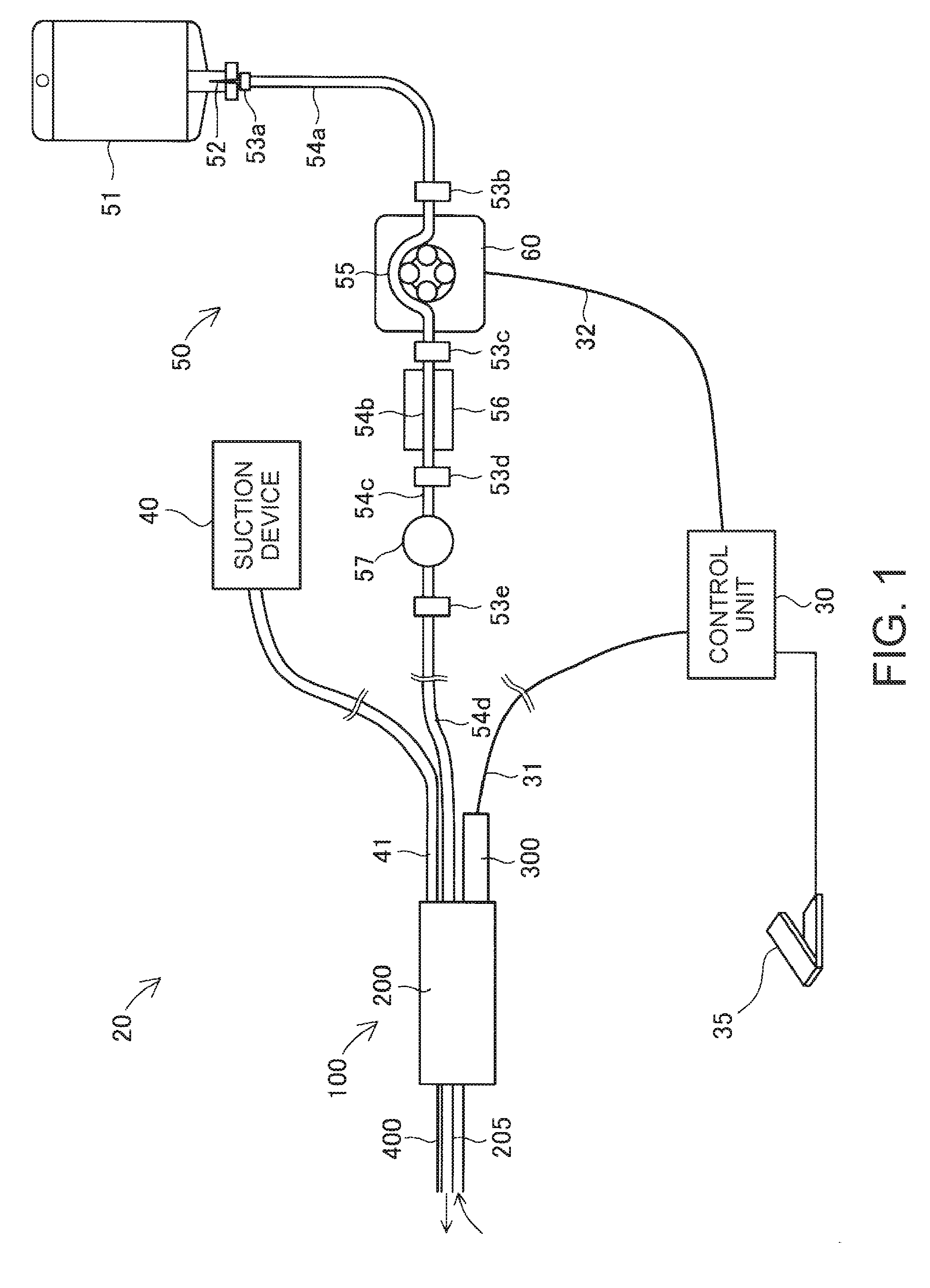
[0040]FIG. 1 schematically illustrates the configuration of the liquid ejection device 20. The liquid ejection device 20 is a medical apparatus used in a medical institution and has a function of excising a diseased part by ejecting a liquid to the diseased part.

[0041]The liquid ejection device 20 includes a control unit 30, an actuator cable 31, a pump cable 32, a foot switch 35, a suction device 40, a suction tube 41, a liquid supply device 50, and a handpiece 100 (operation unit).

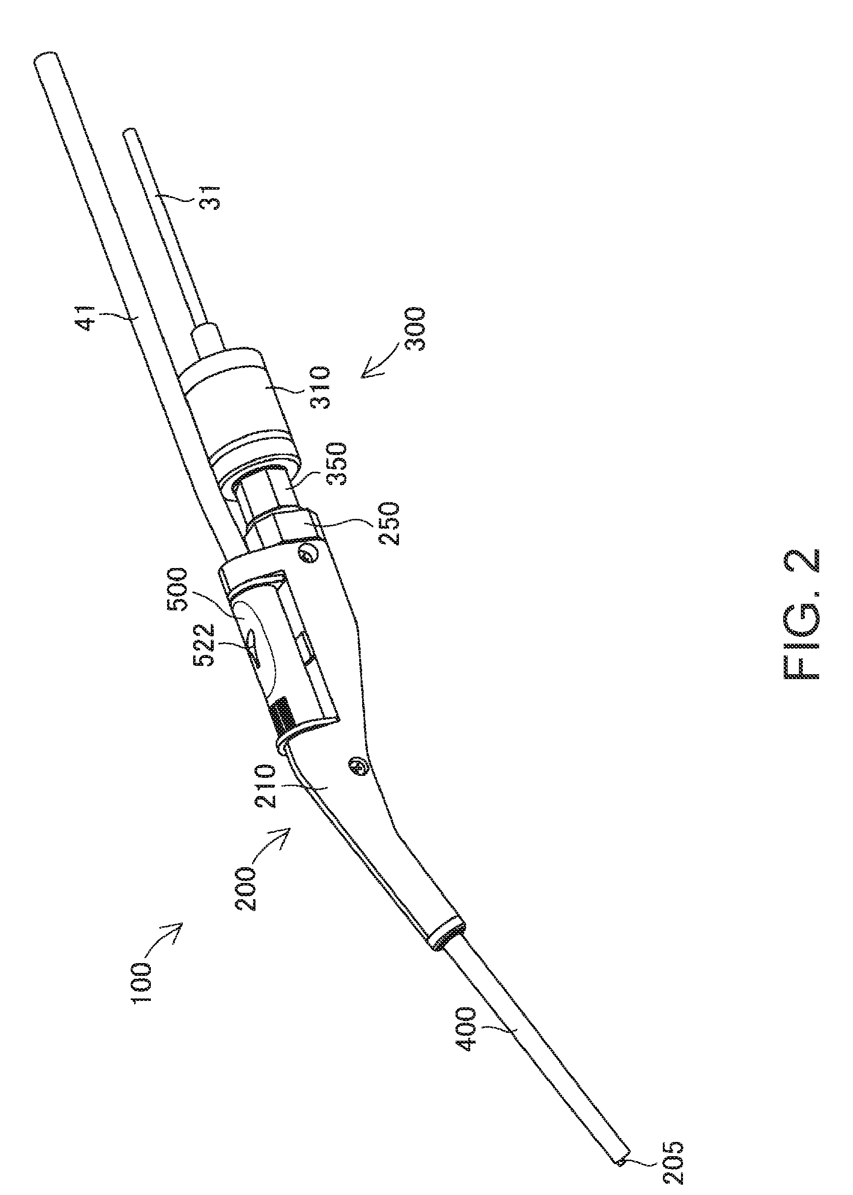
[0042]The liquid supply device 50 includes a water feed bag 51, a spike needle 52, a first connector 53a to a fifth connector 53e, a first water feed tube 54a to a fourth water feed tube 54d, a pump tube 55, a blockade detection mechanism 56, and a filter 57. The handpiece 100 includes a nozzle unit 200 and an actuator unit 300. ...


PUM


Abstract

A liquid supply device includes a pump tube that supplies a liquid to a handpiece intermittently ejecting the liquid and a tube pump that passes the pump tube to supply the liquid. An internal diameter of the pump tube is equal to or less than φ 1.0 mm.

Description

BACKGROUND[0001]1. Technical Field[0002]The present invention relates to supply of a liquid.[0003]2. Related Art[0004]Devices which supply liquids to handpieces intermittently ejecting the liquids are known (see JP-A-2014-95353). The liquid supply device disclosed in JP-A-2014-95353 includes two plunger pumps. Pulsation of a liquid to be supplied is reduced by causing the two plunger pumps to alternately supply the liquid.[0005]In the case of the technology of the foregoing related art, it takes some labor and time to perform maintenance of the plunger pumps. In particular, when the plunger pumps are used for medical treatment, problems particularly occur in cases in which exchange or sterilization is necessary.SUMMARY[0006]An advantage of some aspects of the invention is that a variation in pressure of a liquid to be supplied is suppressed with a mechanism for which maintenance is simple in consideration of the technology of the related art.[0007]The invention can be implemented as...

Claims


Application Information

Patent Timeline
Patent Type & Authority Applications(United States)
IPC IPC(8): B41J2/175
CPCB41J2/17596B41J2/175A61B2018/0091A61M5/1422F04B11/005A61B17/1644A61B17/1628A61B17/3203
Inventor MIYAMOTO, SATORUYAMASAKI, SOSUKE
Owner COLUMBIA PEAK VENTURES LLC
Why Eureka
Try Eureka