Automated differential lock

a technology of differential lock and lock plate, which is applied in the direction of vehicle components, brake systems, propulsion unit safety devices, etc., can solve the problems of more frequent maintenance and high cost, and achieve the effect of increasing longitudinal and lateral traction and improving vehicle handling

Active Publication Date: 2016-09-22
INT TRUCK INTPROP LLC
View PDF1 Cites 6 Cited by
  • Summary
  • Abstract
  • Description
  • Claims
  • Application Information

AI Technical Summary

Benefits of technology

[0008]The differential locking axle of the present disclosure can automatically lock and unlock at any vehicle speed, up to a predetermined maximum speed, or any wheel spin rate up to a predetermined maximum, when a vehicle is being steered either in a straight line or around a curve. That capability enhances vehicle handling by increasing longitudinal and lateral traction.

Problems solved by technology

Consequently, there is little or no axle weight increase, avoiding weight penalty likely imposed by “limited slip” or “no-spin” type locking differential drive axles, which may also be more costly and prone to more frequent maintenance.

Method used


Image

  • Automated differential lock
  • Automated differential lock
  • Automated differential lock

Examples


Embodiment Construction

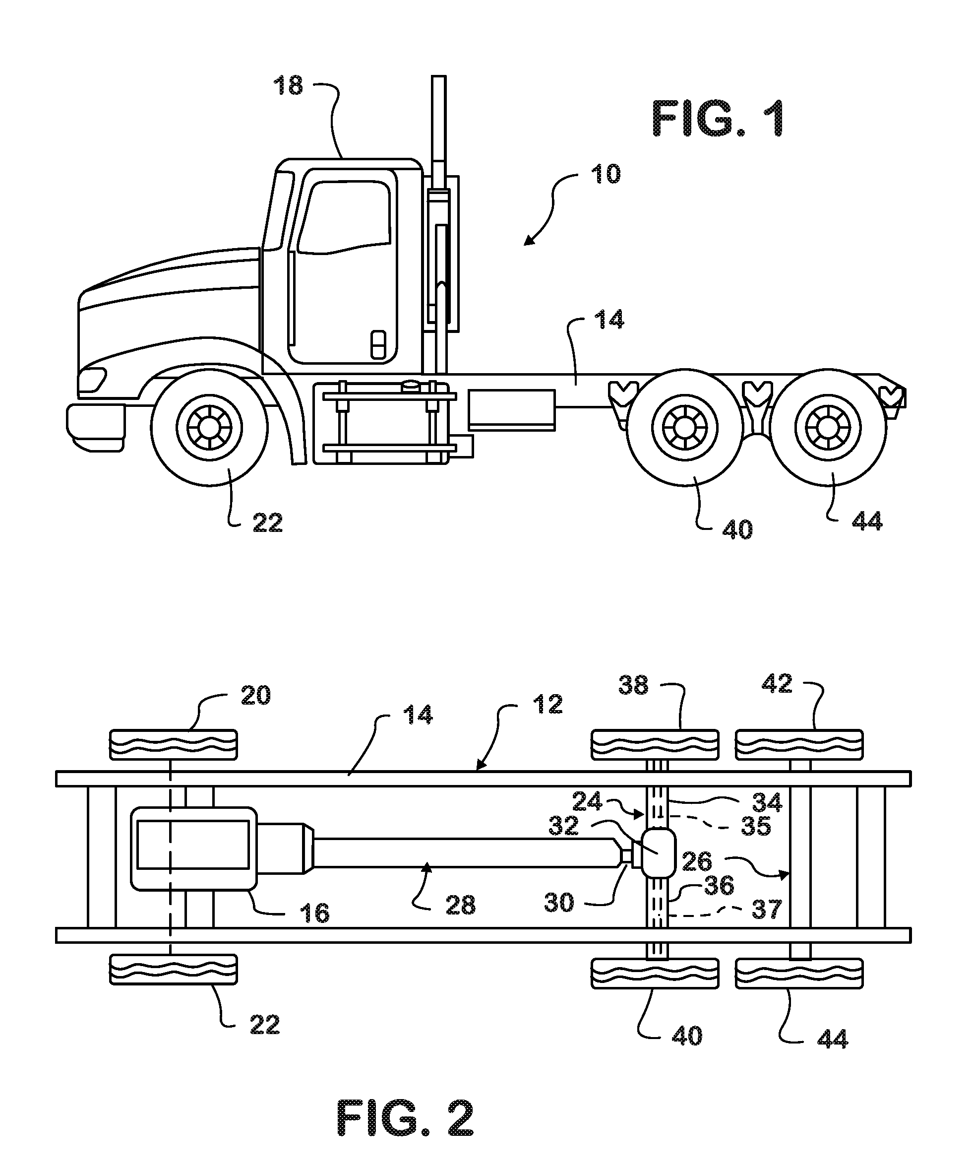
[0022]FIGS. 1 and 2 show an example of a truck vehicle 10 which comprises a chassis 12 having a chassis frame 14 on which are mounted a prime mover, such as a diesel engine, 16 and a cab 18 having an interior compartment for a driver of the truck vehicle. Right and left front steerable wheels 20, 22 respectively are suspended from chassis frame 14 on right and left sides for steering truck vehicle 10.

[0023]Front and rear tandem axles 24, 26 are suspended from chassis frame 14. Front tandem axle 24 is a locking differential drive axle and rear tandem axle 26 is a tag axle. A tag axle can be either to the rear of a drive axle (as shown) or in front of a drive axle, and the locking differential feature can apply to any number of drive axle and tag axle combinations, such as tandems, tridems, etc.

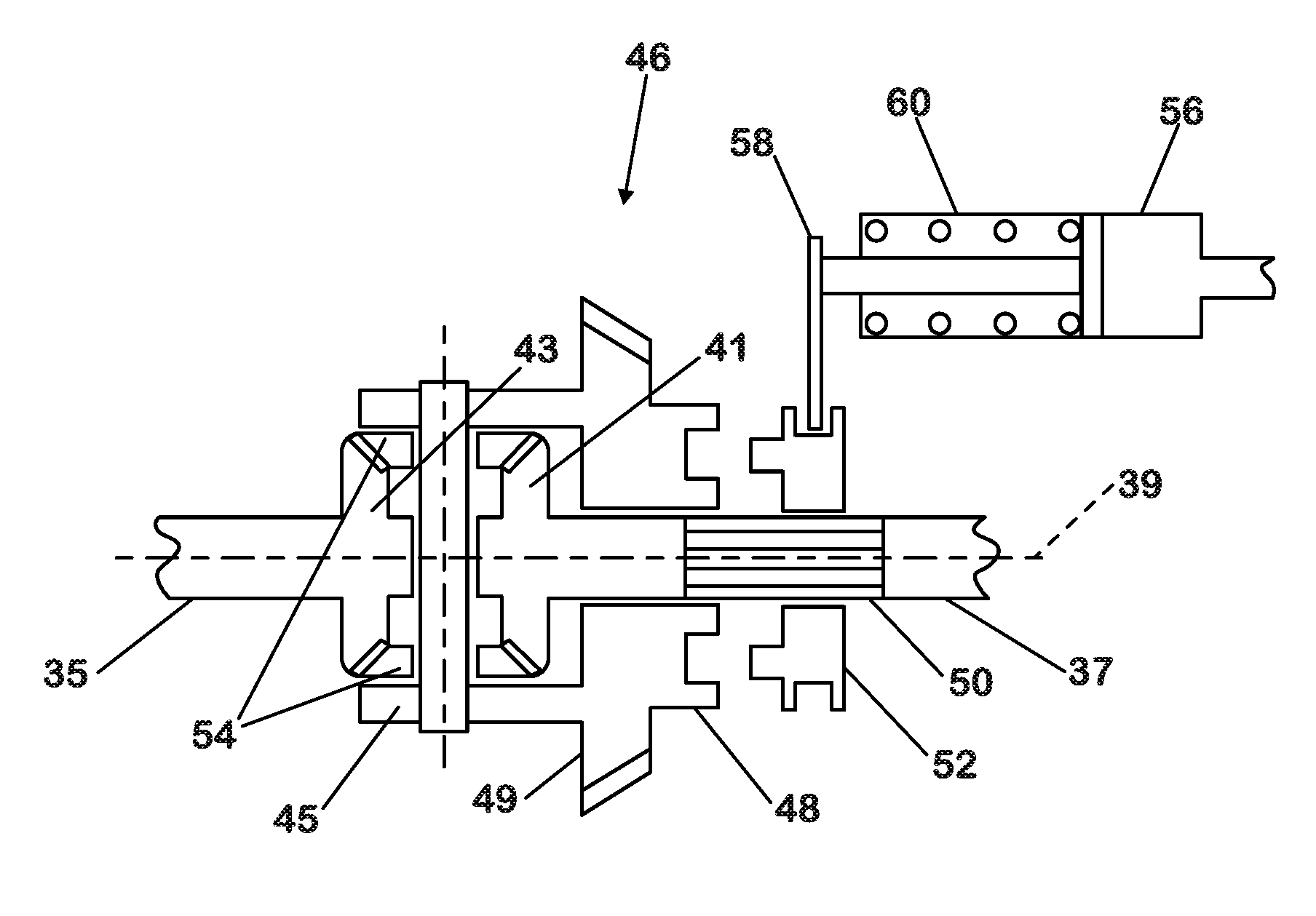
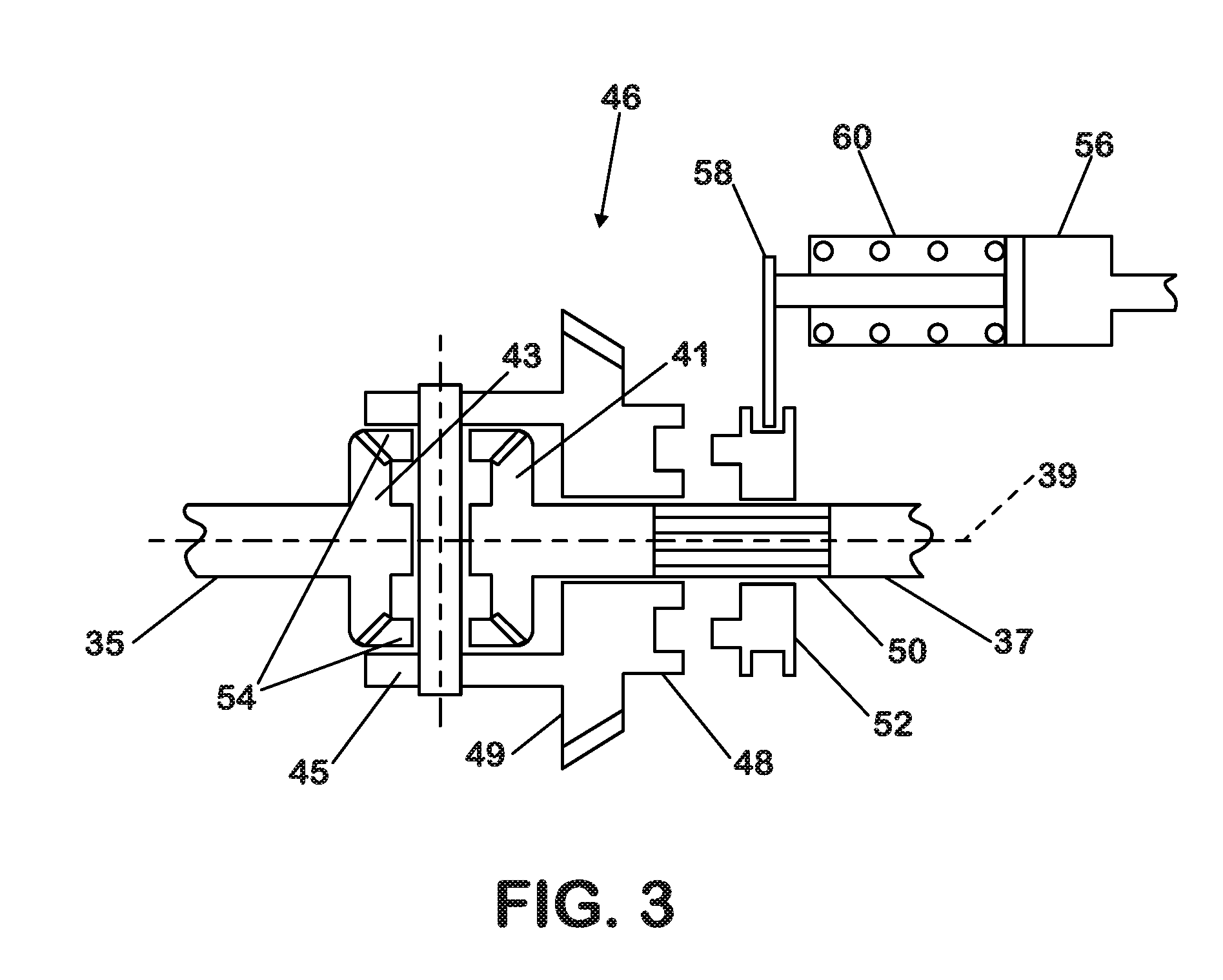
[0024]Prime mover 16 has an output shaft which is coupled through a drivetrain 28 to an input shaft 30 of drive axle 24. Drive axle 24 has a casing 32 which contains a differential gear mechani...


PUM


Abstract

A differential locking axle control system that can cause the axle to automatically lock and unlock at any vehicle speed, up to a predetermined maximum speed, or any wheel spin rate up to a predetermined maximum, when a vehicle is being steered either in a straight line or around a curve while taking traction and global positioning factors into account.

Description

TECHNICAL FIELD[0001]This disclosure relates generally to road and off-road vehicles, particularly to an automatic locking / unlocking differential drive axle of such vehicles.BACKGROUND[0002]A drive axle of a road or off-road vehicle typically has a differential gear mechanism which enables its right and left drive wheels to rotate at different speeds during certain conditions including steering of the vehicle along a turning radius and occurrence of a difference between traction of one drive wheel to an underlying surface and traction of the other drive wheel to an underlying surface. When a drive axle has a locking differential, it includes a locking / unlocking mechanism. When the locking / unlocking mechanism is unlocked, the differential gear mechanism operates as described. When the locking / unlocking mechanism is unlocked, the right and left axle shafts are locked together to cause the right and left drive wheels to rotate in unison and thereby disable their rotation at different s...

Claims


Application Information

Patent Timeline
Patent Type & Authority Applications(United States)
IPC IPC(8): B60T8/32B60T8/176B60T8/175
CPCB60T8/321B60T8/176B60T8/175B60T8/3205B60T8/3215B60T2201/14B60T2210/16
Inventor KORSON, JAMES JEROMESIUCHTA, GRZEGORZ
Owner INT TRUCK INTPROP LLC
Why Eureka
Try Eureka