
Bulkhead assembly having a pivotable electric contact component and integrated ground apparatus

a technology of electric contact and bulb assembly, which is applied in the direction of fluid removal, survey, and borehole/well accessories, etc., can solve the problems of difficult wiring through the perforating gun assembly, easy twisting and crimping during assembly, and source of intermittent and/or failed electrical conta

Active Publication Date: 2016-09-22
DYNAENERGETICS
View PDF30 Cites 65 Cited by
  • Summary
  • Abstract
  • Description
  • Claims
  • Application Information

AI Technical Summary

Benefits of technology

The patent text describes a bulkhead assembly that can withstand high pressure and has an electrical contact component that can make electrical connections and feed through signals. The assembly includes a body that seals components and an electrical contact component with pins that move within the assembly. The bulkhead assembly can be used in a downhole tool and a ground apparatus can be added for better electrical connection. The technical effect of this patent is to provide a reliable and flexible way to connect electrically in high-pressure settings.

Problems solved by technology

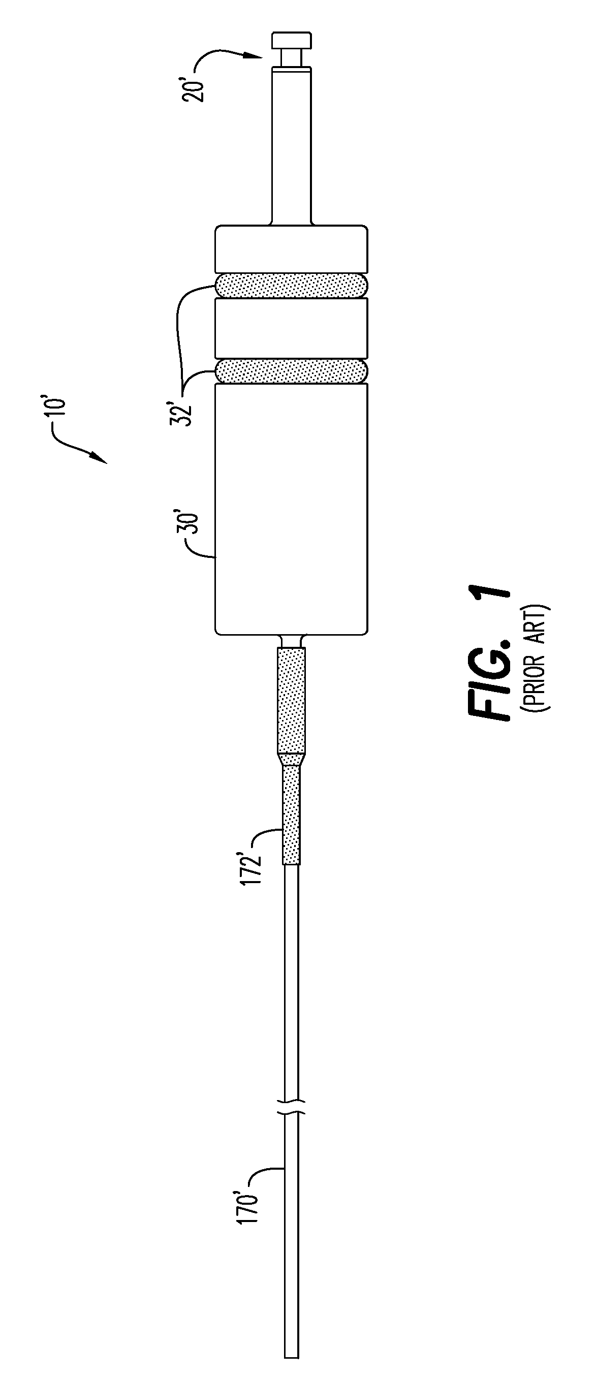
Passage of such wires through the perforating gun assembly, while maintaining a pressure differential across individual components, has proved challenging.
Since the wired electrical connection often must extend through all of the perforating gun assembly, it is easily twisted and crimped during assembly.
One issue with this arrangement is that it can be a source of intermittent and / or failed electrical contact.
In addition, when a wired detonator is used it must be manually connected to the electrical wire, which has lead to multiple problems.
Due to the rotating assembly of parts, the electrical ground wires can become compromised, that is to say the electrical ground wires can become torn, twisted and / or crimped / nicked, or the wires may be inadvertently disconnected, or even mis-connected in error during assembly, not to mention the safety issues associated with physically and manually wiring live explosives.

Method used


Image

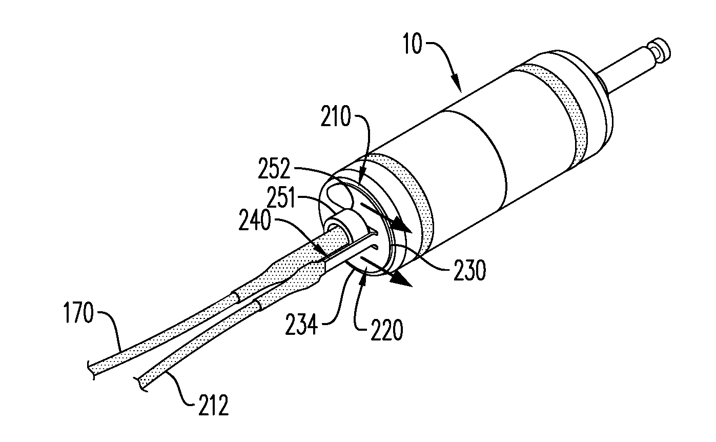
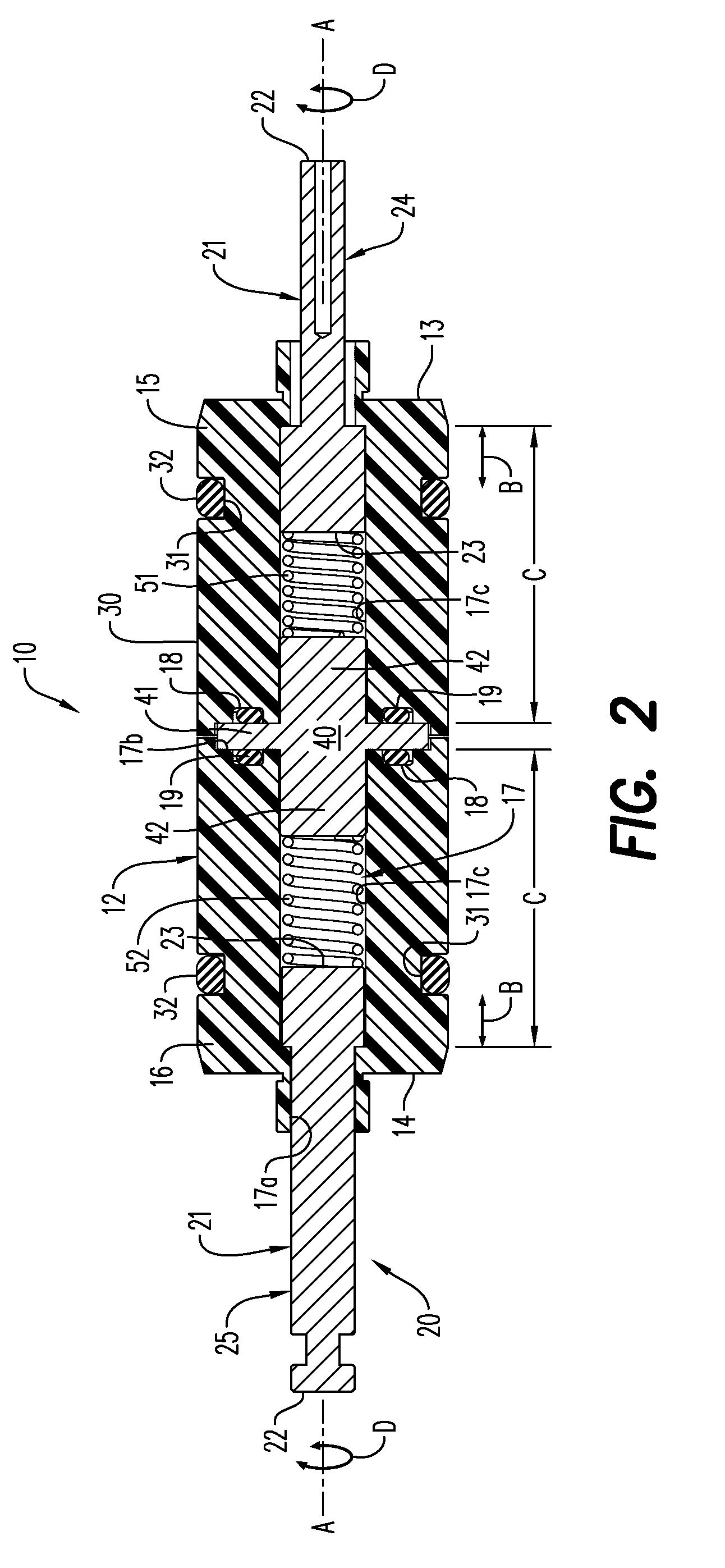
  • Bulkhead assembly having a pivotable electric contact component and integrated ground apparatus
  • Bulkhead assembly having a pivotable electric contact component and integrated ground apparatus
  • Bulkhead assembly having a pivotable electric contact component and integrated ground apparatus

Examples


Embodiment Construction

[0029]Reference will now be made in detail to various embodiments. Each example is provided by way of explanation, and is not meant as a limitation and does not constitute a definition of all possible embodiments.

[0030]A bulkhead assembly is generally described herein, having particular use in conjunction with a downhole tool, and in particular to applications requiring the bulkhead assembly to maintain a pressure, and is thus commonly referred to as a pressure bulkhead assembly. In an embodiment, the bulkhead assembly is configured for use with a logging tool or a perforating gun assembly, in particular for oil well drilling applications. The bulkhead assembly provides an electrical contact component disposed within a body thereof, wherein at least a portion of the electrical contact component is configured to pivot about its own axis, without compromising its ability to provide a pressure and fluid barrier. A ground apparatus is generally described herein. The ground apparatus may...


PUM


Abstract

According to an aspect a bulkhead assembly is provided having particular application with a downhole tool, in particular for oil well drilling applications. The bulkhead assembly includes a bulkhead body and an electrical contact component disposed within the bulkhead body, wherein at least a portion of the electrical contact component is configured to pivot about its own axis, without compromising its ability to provide a pressure and fluid barrier. In an embodiment, a ground apparatus is provided to provide an electrical connection for at least one ground wire. The ground apparatus may be positionable on the bulkhead body of the bulkhead assembly. In an aspect, a downhole tool including the bulkhead assembly and ground apparatus is also generally described.

Description

CROSS-REFERENCE TO RELATED APPLICATIONS[0001]This application claims benefit of U.S. Provisional Application No. 62 / 134,893 filed Mar. 18, 2015, which is incorporated herein by reference in its entirety.FIELD[0002]Described generally herein is a bulkhead assembly having a pivotable electric contact component for use with a downhole tool, that is, any piece of equipment that is used in a well.BACKGROUND[0003]In exploration and extraction of hydrocarbons, such as fossil fuels (e.g. oil) and natural gas, from underground wellbores extending deeply below the surface, various downhole tools are inserted below the ground surface and include sometimes complex machinery and explosive devices. Examples of the types of equipment useful in exploration and extraction, in particular for oil well drilling applications, include logging tools and perforation gun systems and assemblies. It is often useful to be able to maintain a pressure across one or more components, (that is, to provide a “pressu...

Claims


Application Information

Patent Timeline
Patent Type & Authority Applications(United States)
IPC IPC(8): F42D1/05E21B43/1185
CPCE21B43/1185F42D1/05E21B43/119E21B47/00E21B49/00F42D1/043F42B3/10F42C19/00F42D1/04
Inventor EITSCHBERGER, CHRISTIAN
Owner DYNAENERGETICS
Learn More