Method for assembling gas sensor, and gas sensor assembly apparatus

Active Publication Date: 2016-09-22
NGK INSULATORS LTD
View PDF7 Cites 11 Cited by
  • Summary
  • Abstract
  • Description
  • Claims
  • Application Information

AI Technical Summary

Benefits of technology

[0011]According to the present invention, the annular mounting parts are always annularly mounted to the element dummy or the sensor element in the assembly of the gas sensor, thus preferably preventing an occurrence of a problem in which the sensor element cannot be assembled due to an occurrence of a positional deviation. Additionally, breakage of the element tip is preferably prevented when the inside of the gas sensor is sealed with a powder compact.
[0012]Pr

Problems solved by technology

Thus, the application of this technique to a sensor element, whose surface at the side of the relevant end is covered with a protective film (protective layer), is not preferred because the

Method used


Image

  • Method for assembling gas sensor, and gas sensor assembly apparatus
  • Method for assembling gas sensor, and gas sensor assembly apparatus
  • Method for assembling gas sensor, and gas sensor assembly apparatus

Examples


Example

Modification of First Embodiment

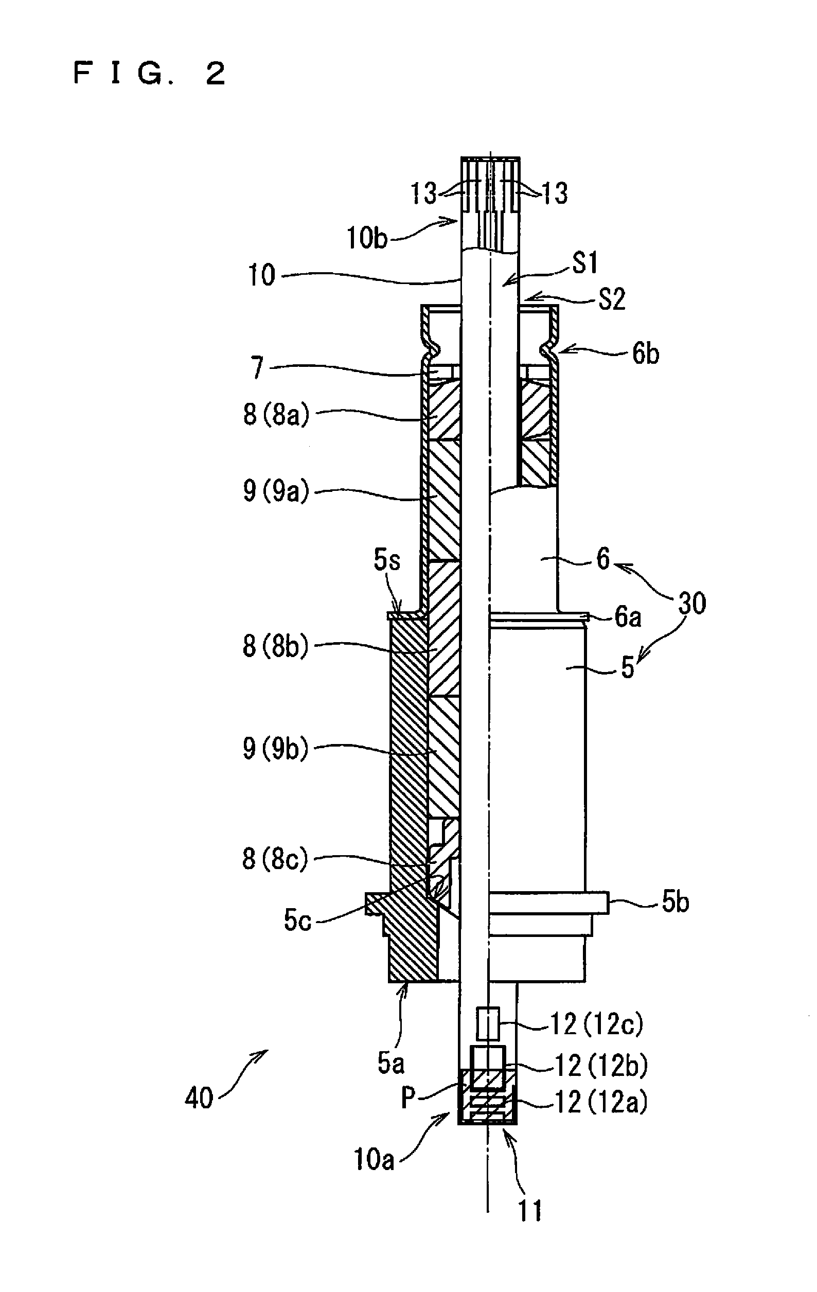
[0089]The assembly apparatus 100 according to the first embodiment is configured as follows: the impact buffer 112 provided at the vertical upper end of the sealing assist jig 111 provides a buffer performance against an impact exerted from vertically above to the sealing assist jig 111, and damage to the protective film P is prevented by performing sealing while causing the protective film P provided at the first tip 10a of the sensor element 10 to be in contact with the impact buffer 112. The configuration of the sealing assist jig 111, however, is not limited to the above and may be any configuration that can mitigate an impact exerted on the protective film P in pressing by the sealing jig 181.

[0090]FIG. 10 schematically shows a sealing assist jig 111 having a configuration different from that of the first embodiment. The sealing assist jig 111 shown in FIG. 10 includes, in its vertical midway portion, an impact buffer 113 formed of an elastic mem...

Example

Second Embodiment

[0093]In the first embodiment and the modification thereof described above, the workpiece 40β is inverted vertically, and then, in sealing the inside of the tubular body 30, the jig that has a buffer performance against an impact exerted from vertically above is used as the sealing assist jig 111 supporting the sensor element 10 from below. This enables sealing without damage to the protective film P and the first tip 10a even when the first tip 10a of the sensor element 10 is provided with the protective film P. The manner of sealing the inside of the tubular body 30, however, is not limited to this. In this embodiment, sealing is performed separately in two stages during assembly of the assembly 40. This will now be described in detail.

[0094]FIG. 11 is a block diagram showing a schematic configuration of an assembly apparatus 1100 that assembles an assembly 40 in this embodiment. Some of the components of the assembly apparatus 1100 are common with the components ...


PUM


Abstract

A method for assembling a gas sensor includes fitting through holes of annular mounting parts with an element dummy disposed vertically and whose cross-sectional shape perpendicular is similar to that of a sensor element. The annular mounting parts are a plurality of parts including a ceramic powder compact. A tubular body is fitted with outer peripheries of the annular mounting parts, and then, the element is abuttingly disposed on an upper end of the dummy. Subsequently, the dummy is moved vertically downward to fit the through holes of the annular mounting parts with the element, thereby obtaining a workpiece. The workpiece is vertically inverted, and with the element tip being in contact with a sealing assist jig that has a buffer performance, the upper end of the uppermost annular mounting part is pressed vertically downward to compress the powder compact, thereby sealing an inside of the tubular body.

Description

BACKGROUND OF THE INVENTION[0001]1. Field of the Invention[0002]The present invention relates to a method for assembling a gas sensor including a ceramic sensor element and to an assembly apparatus for use in assembling the same.[0003]2. Description of the Background Art[0004]A gas sensor including a sensor element formed of oxygen-ion conductive solid electrolyte ceramic such as zirconia (ZrO2) has been conventionally known as a device that measures the concentration of a predetermined gas component of a measurement gas such as an exhaust gas and a combustion gas in an internal combustion engine, usually a car engine.[0005]In such a gas sensor, an elongated-plate-shaped ceramic sensor element (detection element) is usually fixed by a plurality of ceramic supporters which are ceramic insulators glass and by ceramic powder compacts each filled between the ceramic supporters, such as talc, and is hermetically sealed with the powder compacts in a metal housing and a hollow portion of a...

Claims


Application Information

Patent Timeline
IPC IPC(8): G01D11/30
CPCG01D11/30G01N27/4078
Inventor HATTORI, TETSUYATANAKA, HIROYUKIKATO, KENJITAKESHITA, SHIGEKI
Owner NGK INSULATORS LTD
Why Eureka
Try Eureka