Vehicle noise reducing assembly

a technology for reducing assembly and vehicle noise, which is applied in the direction of vehicle components, superstructure subunits, transportation and packaging, etc., can solve the problems of increasing the undesirability or distraction factor of the resulting sound, and undesirable sound entering,

Active Publication Date: 2016-09-29
NISSAN MOTOR CO LTD
View PDF0 Cites 3 Cited by
  • Summary
  • Abstract
  • Description
  • Claims
  • Application Information

AI Technical Summary

Benefits of technology

This patent describes a way to reduce noise in vehicles that have a trunk or cargo space. It involves adding a layer of insulation called a barrier inside the trunk's walls to block out sounds coming from outside. There are also vents and other measures taken to keep air flowing properly within the trunk while minimizing noise. Overall, this helps create a quieter environment for drivers and their passengers when they use the car's trunk.

Problems solved by technology

The technical problem addressed in this patent text pertains to reducing unwanted noise that enters vehicles through the pressure relief valves used for controlling airflow. This issue may cause inconvenience or even danger for drivers and passengers alike.

Method used


Image

  • Vehicle noise reducing assembly
  • Vehicle noise reducing assembly
  • Vehicle noise reducing assembly

Examples


Embodiment Construction

[0016]Selected exemplary embodiments will now be explained with reference to the drawings. It will be apparent to those skilled in the art from this disclosure that the following descriptions of the exemplary embodiments are provided for illustration only and not for the purpose of limiting the invention as defined by the appended claims and their equivalents.

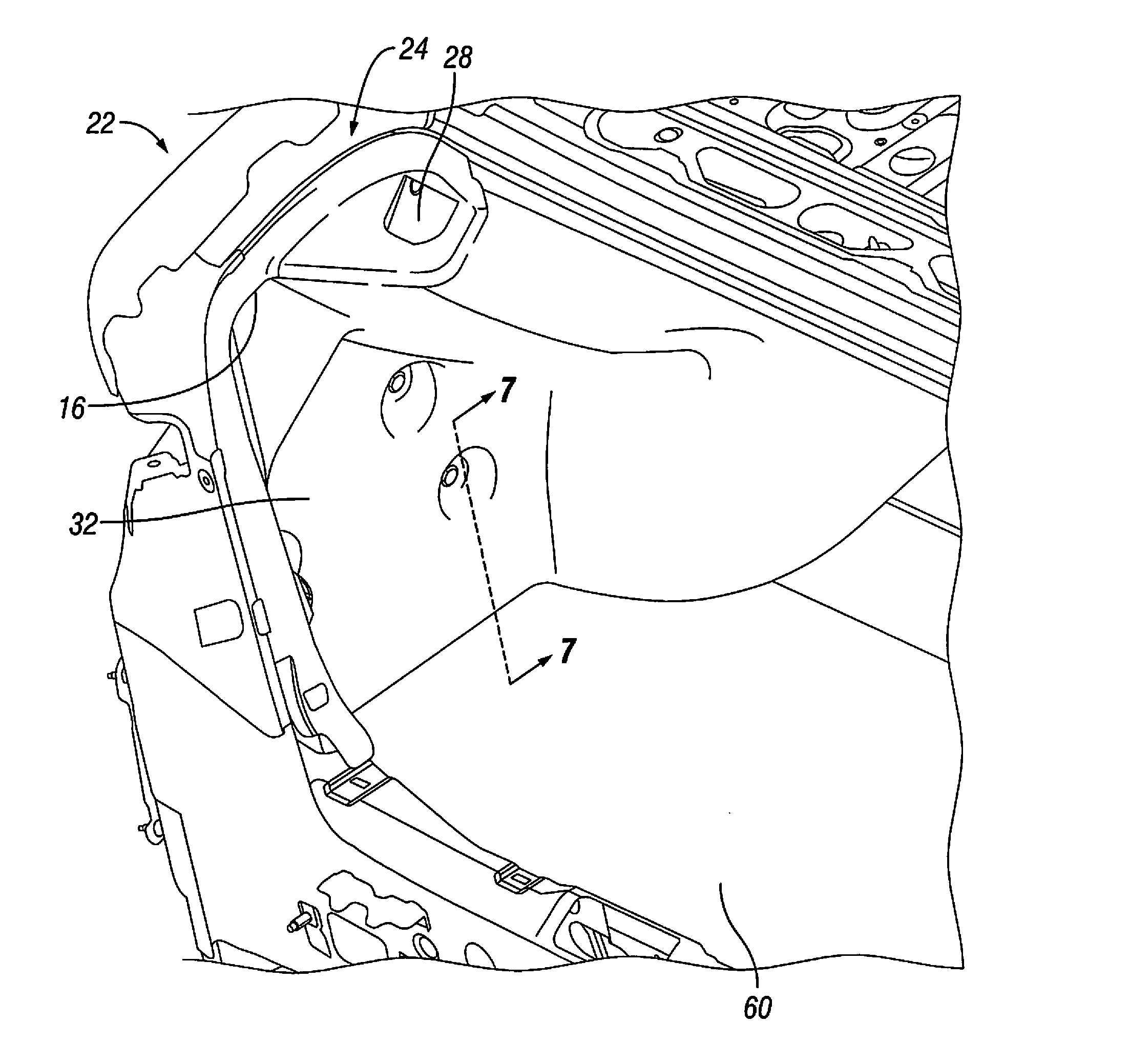
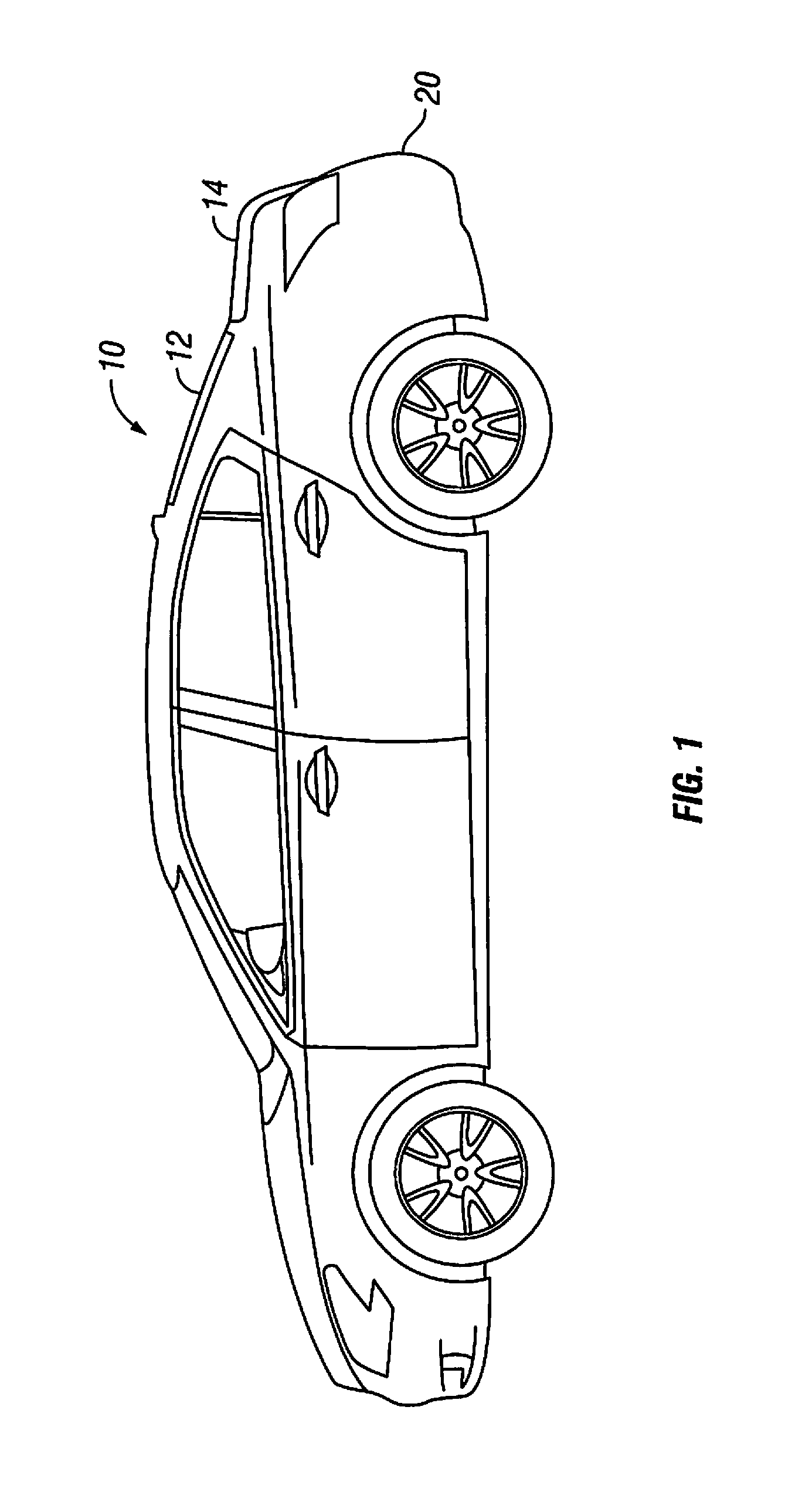
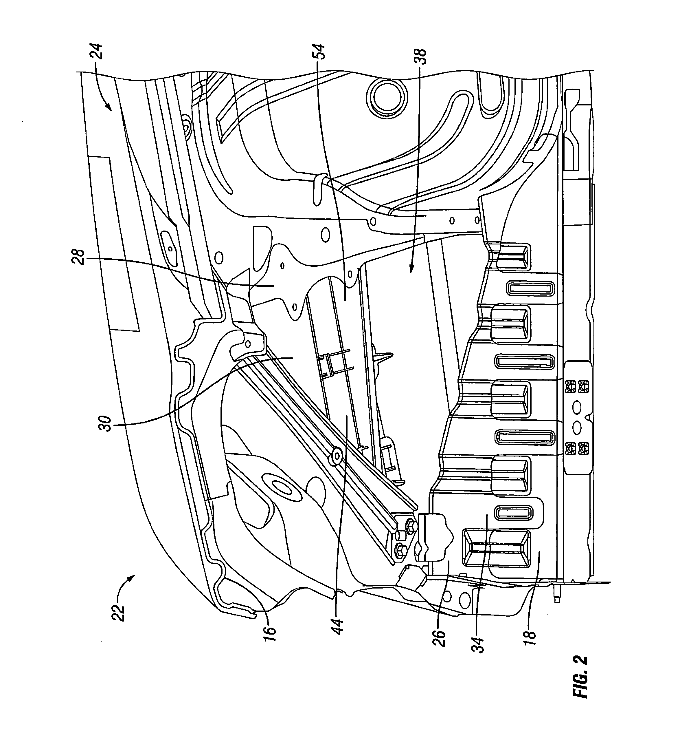
[0017]Referring initially to FIGS. 1, 2 and 8, a vehicle 10 is illustrated in accordance with an exemplary embodiment of the present invention. The vehicle 10 includes, among other features, a vehicle body structure 12 with a trunk lid 14, a trunk opening 16, a trunk storage area 18 and a rear bumper fascia 20. As shown in FIG. 2, the trunk opening 16 exposes the trunk storage area 18 with the trunk lid 14 in an open orientation. The trunk lid 14 is shown in a closed orientation in FIG. 1, but is completely removed from the vehicle 10 in FIG. 2 to provide a view of the trunk storage area 18 within the vehicle body structure 12....


PUM


Abstract

A vehicle noise reducing assembly includes a trunk structure having a floor panel, an interior wall panel and an exterior wall panel. A trunk storage area is defined by the interior wall panel and the floor panel. A trim panel is connected to the interior wall panel within the trunk storage area. A cavity is defined by the floor panel, the exterior wall panel and the trim panel and has a first cavity and a second cavity. A relief valve is disposed in a vent opening in the exterior wall panel. The relief valve extends into the first cavity and has a drafter opening facing inboard. A barrier member is disposed in the second cavity with a barrier surface positioned between the relief valve and the second cavity to prevent sound passing through the drafter opening from entering the second cavity.

Description


Claims


Application Information

Patent Timeline
Owner NISSAN MOTOR CO LTD
Why Eureka
Try Eureka