Method and systems for a multi-fuel engine

a multi-fuel engine and engine technology, applied in the field of engine systems, can solve problems such as limiting the opportunities of operating engines with natural gas

Active Publication Date: 2016-09-29
GE GLOBAL SOURCING LLC
View PDF10 Cites 17 Cited by
  • Summary
  • Abstract
  • Description
  • Claims
  • Application Information

AI Technical Summary

Problems solved by technology

However, many existing engines are typically configured with only a single, liquid (e.g., diesel) fuel supply, limiting the opportunities for operating engines with natural gas.

Method used


Image

  • Method and systems for a multi-fuel engine
  • Method and systems for a multi-fuel engine
  • Method and systems for a multi-fuel engine

Examples


Embodiment Construction

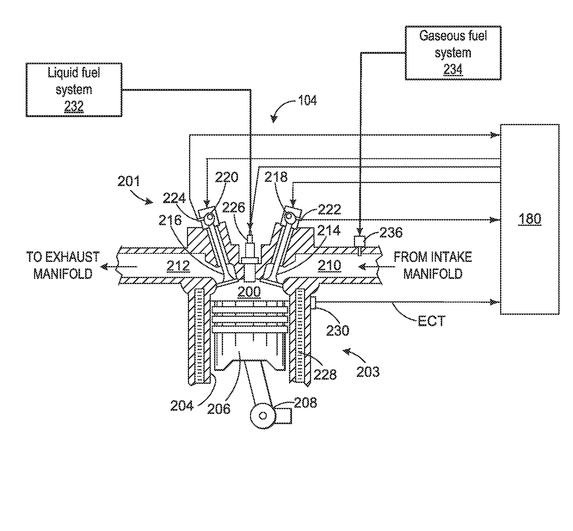
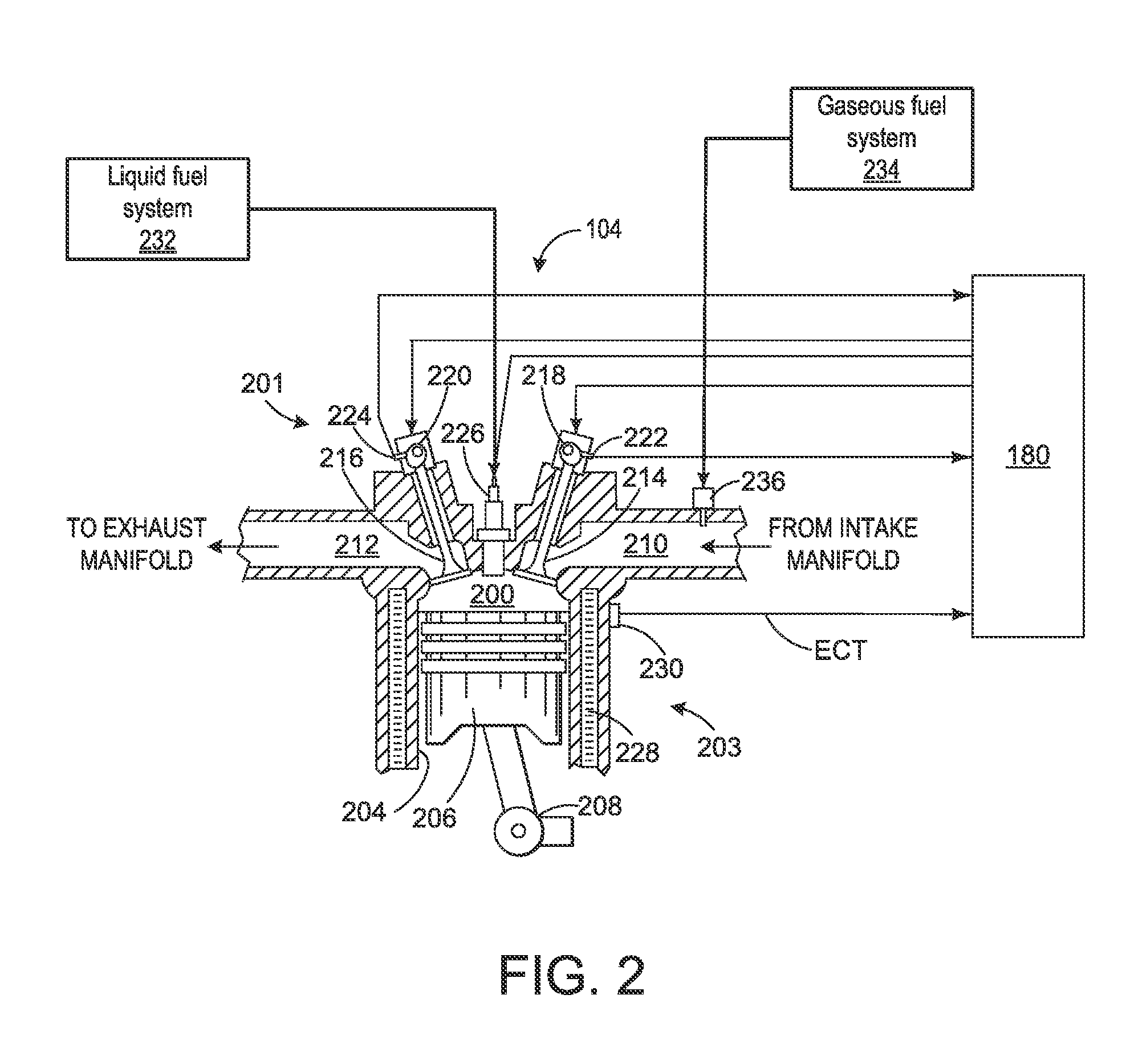
[0014]The following description relates to embodiments of adjusting intake valve closing timing in an engine configured to operate with liquid fuel only (e.g., diesel fuel only) and with both liquid fuel and gaseous fuel (e.g., diesel and natural gas). During operation with only liquid fuel, the intake valve closing timing may be adjusted based on engine load in order to increase engine efficiency and decrease fuel consumption and emissions at both high and low loads. During operation with both liquid fuel and gaseous fuel, the intake valve closing timing may be adjusted to a timing that may be different than the timing during liquid fuel only operation. For example, during the multi-fuel mode, an earlier timing may be used to reduce compressed gas temperatures and enable operation at higher gaseous fuel rates.

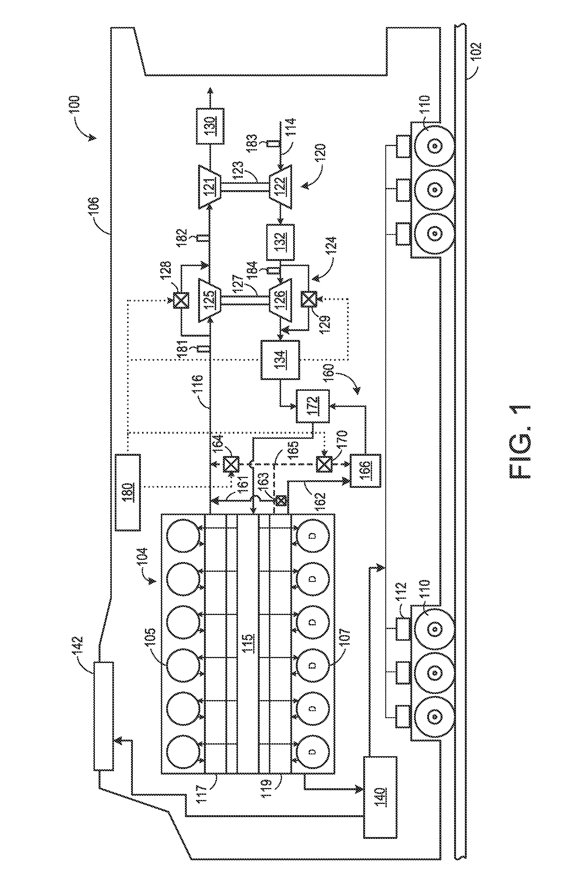
[0015]The multi-fuel capable engine described above may be utilized as the prime mover of a vehicle, such as the rail vehicle depicted in FIG. 1, and may be part of an engine ...


PUM


Abstract

Various methods and systems are provided for a multi-fuel capable engine. In one example, a system comprises an engine having at least one cylinder controlled via an intake valve, a first fuel system to deliver liquid fuel and a second fuel system to deliver gaseous fuel to the at least one cylinder, a variable valve timing actuation system to adjust one or more of an opening or a closing timing of the intake valve, and a controller. The controller is configured to, during a liquid fuel only mode, adjust the variable valve timing actuation system to close the intake valve at a first timing based at least on engine load, and during a multi-fuel mode, adjust the variable valve timing actuation system to close the intake valve at a second timing.

Description

BACKGROUND[0001]1. Technical Field[0002]Embodiments of the subject matter disclosed herein relate to an engine system.[0003]2. Discussion of Art[0004]In light of its favorable energy content, natural gas may be used as a fuel source for an engine. However, many existing engines are typically configured with only a single, liquid (e.g., diesel) fuel supply, limiting the opportunities for operating engines with natural gas. When engines are configured to operate with both liquid and gaseous fuel, a trade-off may be made between an optimal compression ratio for liquid versus gaseous fuel operation. For example, a high compression ratio may be preferred for liquid fuel engines in order to provide reliable starting, low power ignition, and high efficiency. In contrast, a lower compression ratio may be preferred for gaseous fuel engines to prevent pre-ignition and allow a high percentage of gaseous fuel substitution at high power levels.BRIEF DESCRIPTION[0005]In one embodiment, a system c...

Claims


Application Information

Patent Timeline
Patent Type & Authority Applications(United States)
IPC IPC(8): F02D19/06
CPCF02D19/0642F02D13/0234F02D13/0269F02D19/0647F02D19/08F02D35/025F02D41/0002F02D41/0025F02D41/0027F02D2041/001F02D2200/0414F02D2200/1002F02D2200/101F02D2200/703Y02T10/12Y02T10/30Y02T10/40F02D19/0673
Inventor FLYNN, PAUL LLOYDNAIK, GANESHA KOGGULAVERTU, THOMAS MICHAELSALAZAR, VICTOR MANUELWILLIS, JEFFREY DAVID
Owner GE GLOBAL SOURCING LLC
Why Eureka
Try Eureka