Centrifugal Compressor and Centrifugal Water Chilling Unit

Active Publication Date: 2016-09-29
GREE ELECTRIC APPLIANCES INC
View PDF10 Cites 7 Cited by
  • Summary
  • Abstract
  • Description
  • Claims
  • Application Information

AI Technical Summary

Benefits of technology

[0019]By means of the technical solutions of the invention, the centrifugal compressor comprises the housing, the adjusting piece, the driving piece and the adjustable diffuser, wherein the housing is provided with the mounting chamber, and the thread section is provided on the side wall of the mounting chamber; the adjusting piece is mounted in the mounting chamber and is provided with the threads adapting to the thread section; the driving piece is mounted in the mounting chamber and drives the adjusting piece to move forwards or backwards along the thread section; and the adjustable diffuser is fixedly connected to

Problems solved by technology

However, since synchronization of the cams driven by the guide blade shaft in the operating process cannot be completely guaranteed, synchronization of contact positions of the cams and the guide rods cannot be completely guaranteed, so that error accumulation is caused, it is quite easily caused that some of the guide rods are moving while the rest d

Method used


Image

  • Centrifugal Compressor and Centrifugal Water Chilling Unit
  • Centrifugal Compressor and Centrifugal Water Chilling Unit
  • Centrifugal Compressor and Centrifugal Water Chilling Unit

Examples


Embodiment Construction

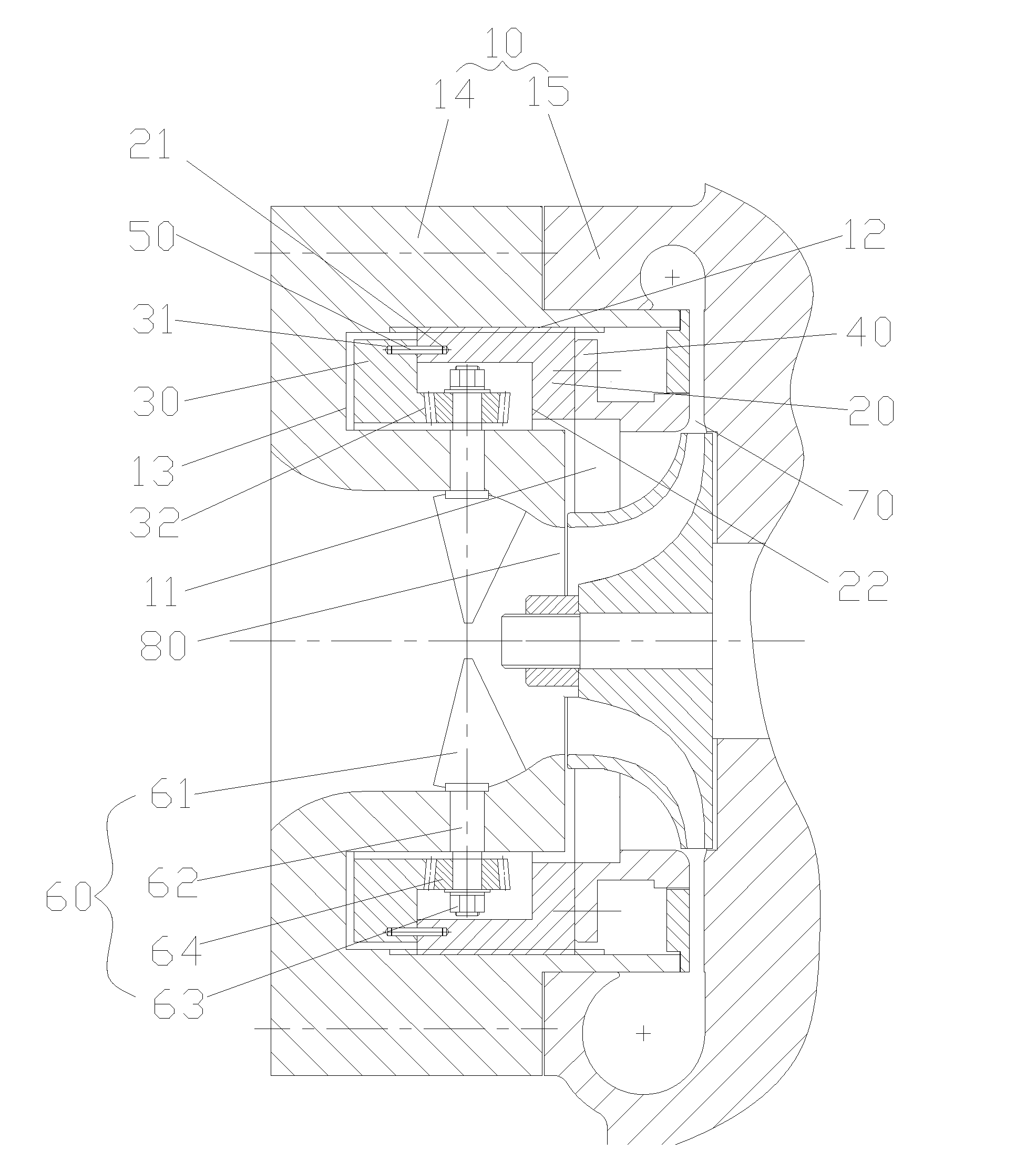
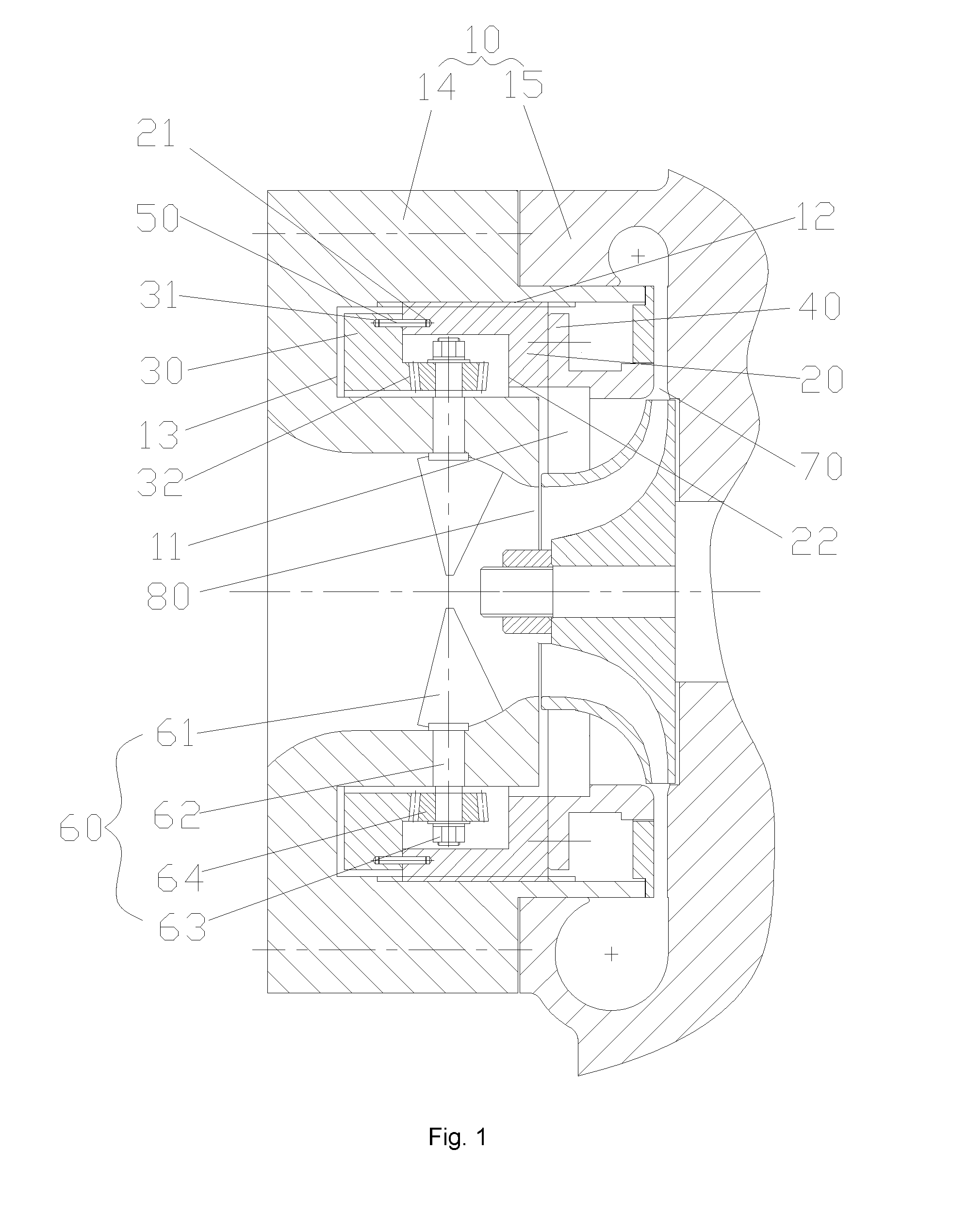
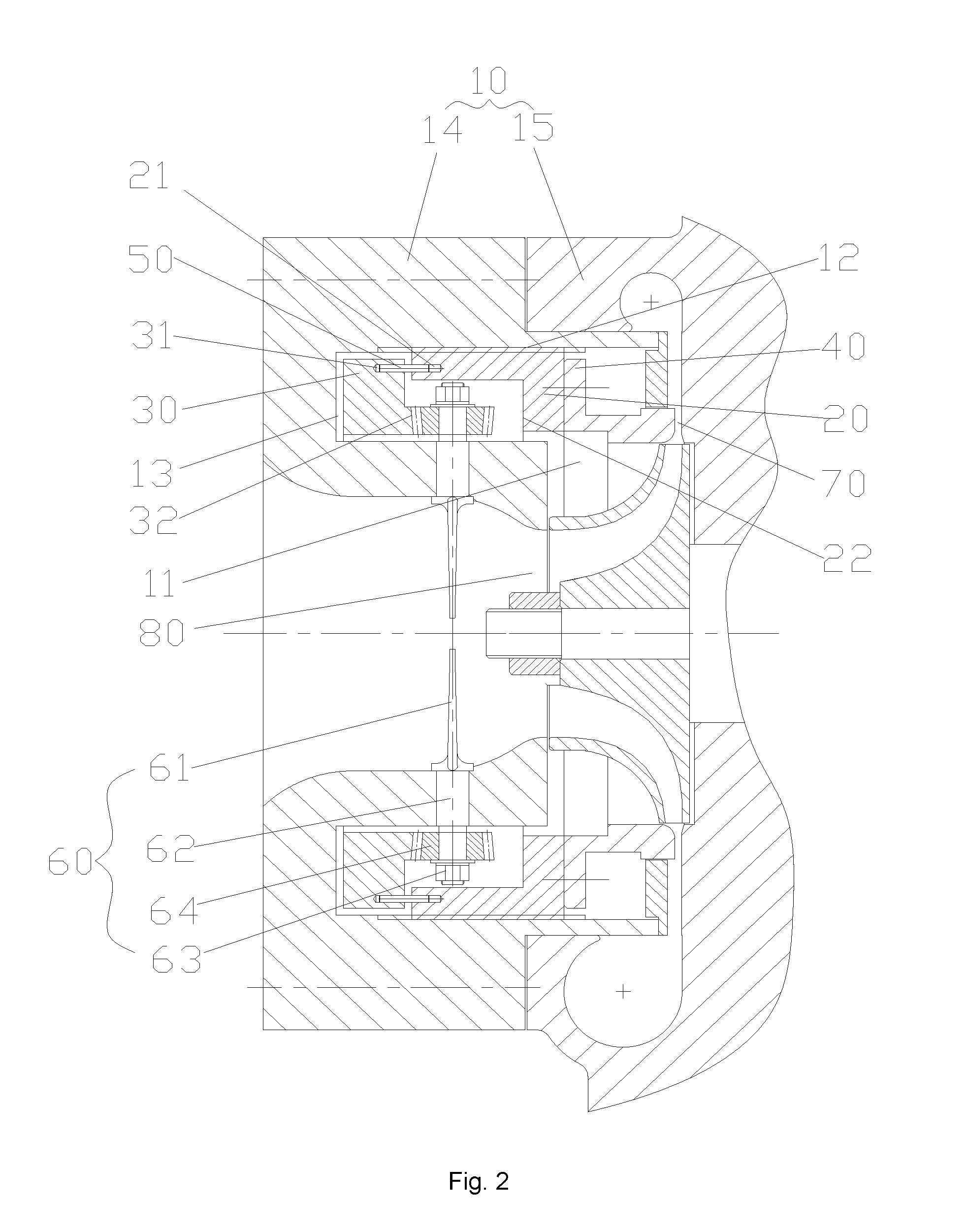
[0024]The embodiments of the invention are described below in detail with reference to the drawings. However, the invention can be implemented in multiple different modes limited and covered by claims.

[0025]As shown in FIG. 1 and FIG. 2, according to an embodiment of the invention, a centrifugal compressor comprises a housing 10, an adjusting piece 20, a driving piece 30 and an adjustable diffuser 40, wherein the housing 10 is provided with a mounting chamber 11, and a thread section 12 is provided on a side wall of the mounting chamber 11; the adjusting piece 20 is mounted in the mounting chamber 11, and the adjusting piece 20 is provided with threads adapting to the thread section 12; the driving piece 30 is mounted in the mounting chamber and drives the adjusting piece 20 to move forwards or backwards along the thread section 12; and the adjustable diffuser 40 is fixedly connected to the adjusting piece 20. In the embodiment, when the driving piece 30 drives the adjusting piece 2...


PUM


Abstract

The invention discloses a centrifugal compressor. The centrifugal compressor comprises: a housing (10), provided with a mounting chamber (11), a thread section (12) being provided on a side wall of the mounting chamber (11); an adjusting piece (20), mounted in the mounting chamber (11), the adjusting piece (20) being provided with threads adapting to the thread section (12); a driving piece (30), mounted in the mounting chamber (11) and configured to drive the adjusting piece (20) to move forwards or backwards along the thread section (12); and an adjustable diffuser (40), fixedly connected to the adjusting piece (20). The invention also discloses a centrifugal water chilling unit having the centrifugal compressor. The centrifugal compressor and the centrifugal water chilling unit can solve the problem that the adjustable diffuser easily inclines and is stuck, thereby greatly improving the reliability of the centrifugal compressor.

Description

TECHNICAL FIELD OF THE INVENTION[0001]The invention relates to the technical field of compressors, and in particular to a centrifugal compressor and a centrifugal water chilling unit.BACKGROUND OF THE INVENTION[0002]When a conventional centrifugal compressor is started, it is often necessary to totally close guide blades so as to prevent a starting current from being over-high. Meanwhile, a flow channel of an impeller outlet diffuser is narrowed. As a motor runs gradually and steadily, the guide blades are opened step by step, and it is necessary to slowly increase the width of the flow channel of the impeller outlet diffuser to a designed width.[0003]In order to achieve a structural mode of this variable-section diffuser, several materials such as cams, guide rods and springs are often added to a position underneath a guide blade shaft, such that the guide blade shaft is pushed by the cams and the guide rods in an operating process, and the guide rods move backwards as needed under...

Claims


Application Information

Patent Timeline
IPC IPC(8): F04D29/46F04D29/42F04D29/28
CPCF04D29/462F04D29/4206F04D29/284F04D17/10F04D29/441F04D29/661F04D29/4213F04D29/464F05D2250/51F05D2250/52F04D29/44
Inventor JIANG, NANZHONG, RUIXINGJIANG, CAIYUNXIE, RONGWANG, HONGXINGLIU, JIANFEICHEN, YUHUI
Owner GREE ELECTRIC APPLIANCES INC
Why Eureka
Try Eureka