This helps you quickly interpret patents by identifying the three key elements:
Problems solved by technology
Method used
Benefits of technology
[0008]This disclosure relates to an O/E module for a daughter card of a backplane connector system that eliminates the fiber cable routing complexity of prior art VPX daughter cards. Specifically, rather than having island-mount opto-electro devices (OEDs), which require complex routing of ribbon cable to optically couple them to optical connectors at the card's edge, the present invention modularizes the O/E functionality, the optical connector and fiber interconnection to provide a compact module for disposition at the card's edge. This modularity is facilitated, at least in part, by the elimination of a biased ferrule in the optical connector on the daughter card. Specifically, the biased ferrule is moved from the card connector of the daughter card to the mating backplane connector so that the axial displacement of the ferrule in the daughter card connector is eliminated, thus essentially eliminating fiber bow/deflection/bending in the module.
[0009]Such a configuration has significant benefits. For example, by locating the OED close to the connector in the module, the optical connection between the connector and the OED is shortened, thus simplifying the interconnection and saving valuable real estate on the daughter card. As discussed above, the short optical interconnect
Problems solved by technology
Computing system designers face significant design challenges for embedded computing technologies, including, for example, reliability of operation, harsh operating environments, system interoperability, and data and system security.
For example, if the bow in the cable assembly is excessive, the cable may interfere with the adjacent daughter cards and/or other cables on the card.
Furthermore, VPX systems are typically used in aircraft and military equipment in which the environments tend to be severe (for example, high-vibration), yet reliability is critical.
Vibration-induced wear, abrasion
Method used
Image
Click on the blue label to locate the original text in one second.
Reading with bidirectional positioning of images and text.
Examples
Example
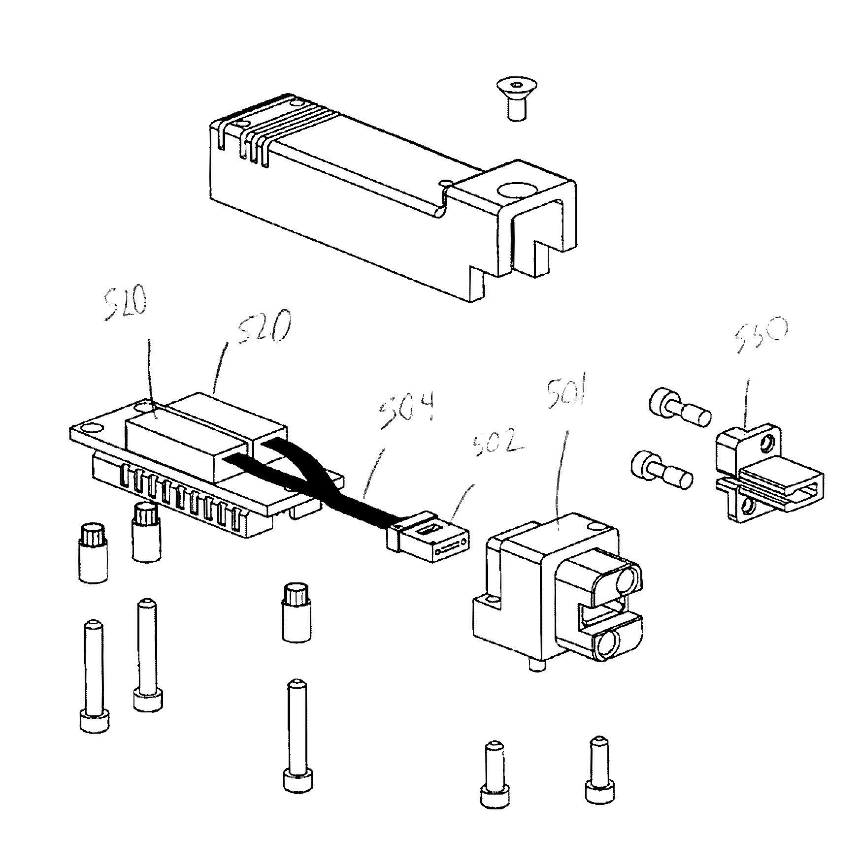
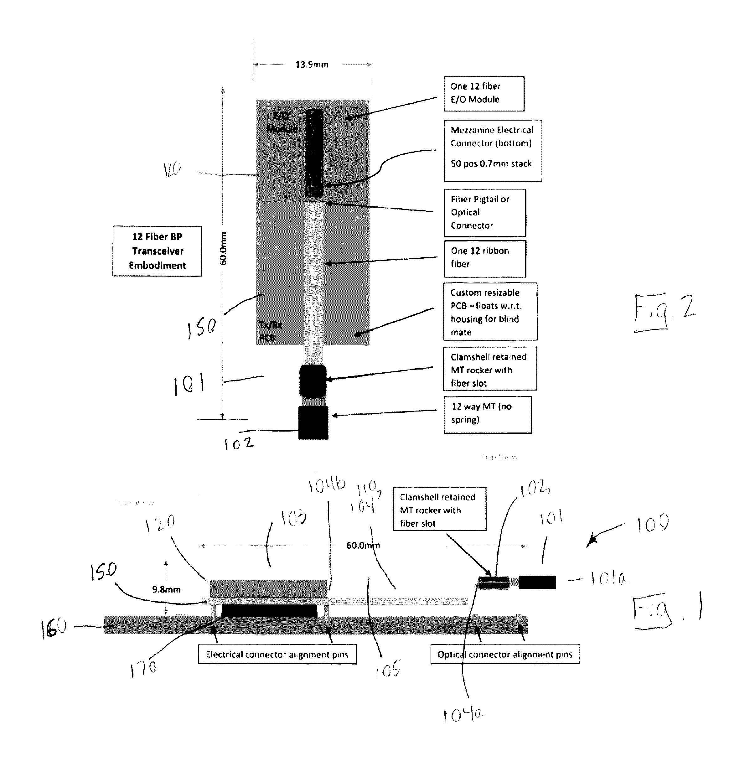
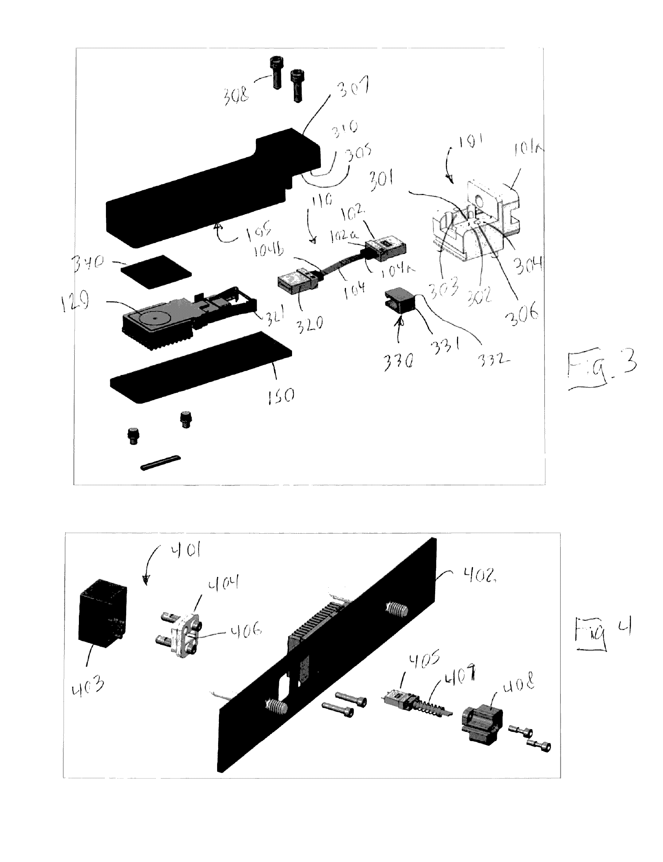
[0020]Referring to FIGS. 1-3, one embodiment of the opto-electric (OE) module 100 of the present invention is shown. The module 100 has a front and back orientation and is suitable for mounting on a daughter card 160. The module comprises a connector 101 having a front end 101a configured to mate with a backplane connector 401 on a backplane 402 (see FIG. 4), and a cavity 301 rearward of the front end to receive a first ferrule 102. In one embodiment, the connector physically / dimensionally complies with VITA 66, and more particularly, VITA 66.4, to ensure dimensional compatibility with existing VPX systems and the ability to be dropped into a VITA defined slot. The cavity 301 is open at the top (see FIG. 3) to provide the first ferrule with access to the cavity prior to the cover 103 being put in place. The connector also comprises a first interface 302 on the periphery 303 of the cavity 301 to mate with a second interface 310 of the cover 103.
[0021]The module 100 also comprises an ...
PUM
Abstract
An opto-electric (OE) module having a front and back orientation and comprising a connector having a front end configured to mate with a connector, an optical interconnect comprising an optical conduit with first and second ends, the first end being terminated by at least one first ferrule, the first ferrule being disposed in the connector in a non-biased state, and the second end being optically coupled to at least one opto-electric device (OED), wherein the optical interconnect is not configured to bend to accommodate distance variations between said first ferrule and said OED, a cover being attached to the connector and having an interior, a circuit board disposed in the interior and having an electrical interface configured to connect to a daughter card, and the opto-electric device (OED) attached to the circuit board and optically connected to the second end.
Description
FIELD OF INVENTION[0001]The subject matter herein relates generally to backplane opto-electrical (O / E) systems, and, more specifically, to O / E modules for backplane connector systems.BACKGROUND[0002]Computing system designers face significant design challenges for embedded computing technologies, including, for example, reliability of operation, harsh operating environments, system interoperability, and data and system security. To meet these challenges, VMEbus International Trade Association (VITA), a standards-development body, has worked to define and develop key computer bus, board, and system specifications, such as VMEbus, PCI Mezzanine Card (PMC), VXS, VPX, and FMC, among others. Of particular interest herein is VPX, formerly known as VITA 46, which is an ANSI standard (ANSI / VITA 46.0-2007). The ANSI / VITA VPX standard defines ruggedized backplane / module card system configurations for embedded computing. Within VPX, the VITA 66 standards (hereby incorporated by reference) defi...
Claims
Application Information
Patent Timeline
Application Date:The date an application was filed.
Publication Date:The date a patent or application was officially published.
First Publication Date:The earliest publication date of a patent with the same application number.
Issue Date:Publication date of the patent grant document.
PCT Entry Date:The Entry date of PCT National Phase.
Estimated Expiry Date:The statutory expiry date of a patent right according to the Patent Law, and it is the longest term of protection that the patent right can achieve without the termination of the patent right due to other reasons(Term extension factor has been taken into account ).
Invalid Date:Actual expiry date is based on effective date or publication date of legal transaction data of invalid patent.