Orthodontic bracket for primary teeth

a technology for orthodontic brackets and primary teeth, which is applied in the direction of brackets, arch wires, etc., can solve the problems of inconvenient patient use, poor oral hygiene, and inability to clean the mouth, so as to prevent the premature dislodging of primary teeth, reduce torque forces, and be easily and comfortably removed

Active Publication Date: 2016-10-06
BERNSTEIN RAEL
View PDF3 Cites 3 Cited by
  • Summary
  • Abstract
  • Description
  • Claims
  • Application Information

AI Technical Summary

Benefits of technology

[0018]One objective of the present disclosure is to provide a cost-efficient bracket for primary teeth which can receive and support an arch wire of an orthodontic patient.
[0019]Another objective of the present disclosure is to help reduce the torque forces applied to primary teeth by an edgewise or rectangular arch wire of an orthodontic patient.
[0020]Another objective of the present di

Problems solved by technology

As such, these appliances can be uncomfortable for the patient as the tongue space is encroached.
Having a lingual expansion appliance in the tongue space can also make speech difficult.
Another problem with lingual expansion appliances is that food can become stuck between the appliances and the roof or floor of the mouth and be difficult to remove, which can potentially cause infection inside the mouth and foul odors.
These appliances also typically apply a large force to the teeth so that arch development can be developed more quickly, which can be painful for the patient.
One problem associated with arch width development in Phase 1 or mixed dentition patients is that traditional brackets and passive self-ligating brackets that can potentially be placed on primary teeth typically include edgewise or rectangular channels that generally conform to the shape of a rectangular arch wire.
The twisting of the large rectangular wires can potentially twist and apply a torque force on the teeth via the bracket, which can cause the primary teeth to prematurely become loose and exfoliate early, which is undesirable.
Additionally, traditional brackets and passive self-ligating brackets are designed for permanent teeth, and therefore can be larger than the facial surface of the primary teeth, which can affect the

Method used


Image

  • Orthodontic bracket for primary teeth
  • Orthodontic bracket for primary teeth
  • Orthodontic bracket for primary teeth

Examples


Embodiment Construction

[0033]While the making and using of various embodiments of the present invention are discussed in detail below, it should be appreciated that the present invention provides many applicable inventive concepts that are embodied in a wide variety of specific contexts. The patentable scope of the invention is defined by the claims, and may include other examples that occur to those skilled in the art. The specific embodiments discussed herein are merely illustrative of specific ways to make and use the invention and do not limit the scope of the invention. Those of ordinary skill in the art will recognize numerous equivalents to the specific apparatus and methods described herein. Such equivalents are considered to be within the scope of this invention and are covered by the claims.

[0034]To facilitate the understanding of the embodiments described herein, a number of terms are defined below. The terms defined herein have meanings as commonly understood by a person of ordinary skill in t...


PUM


Abstract

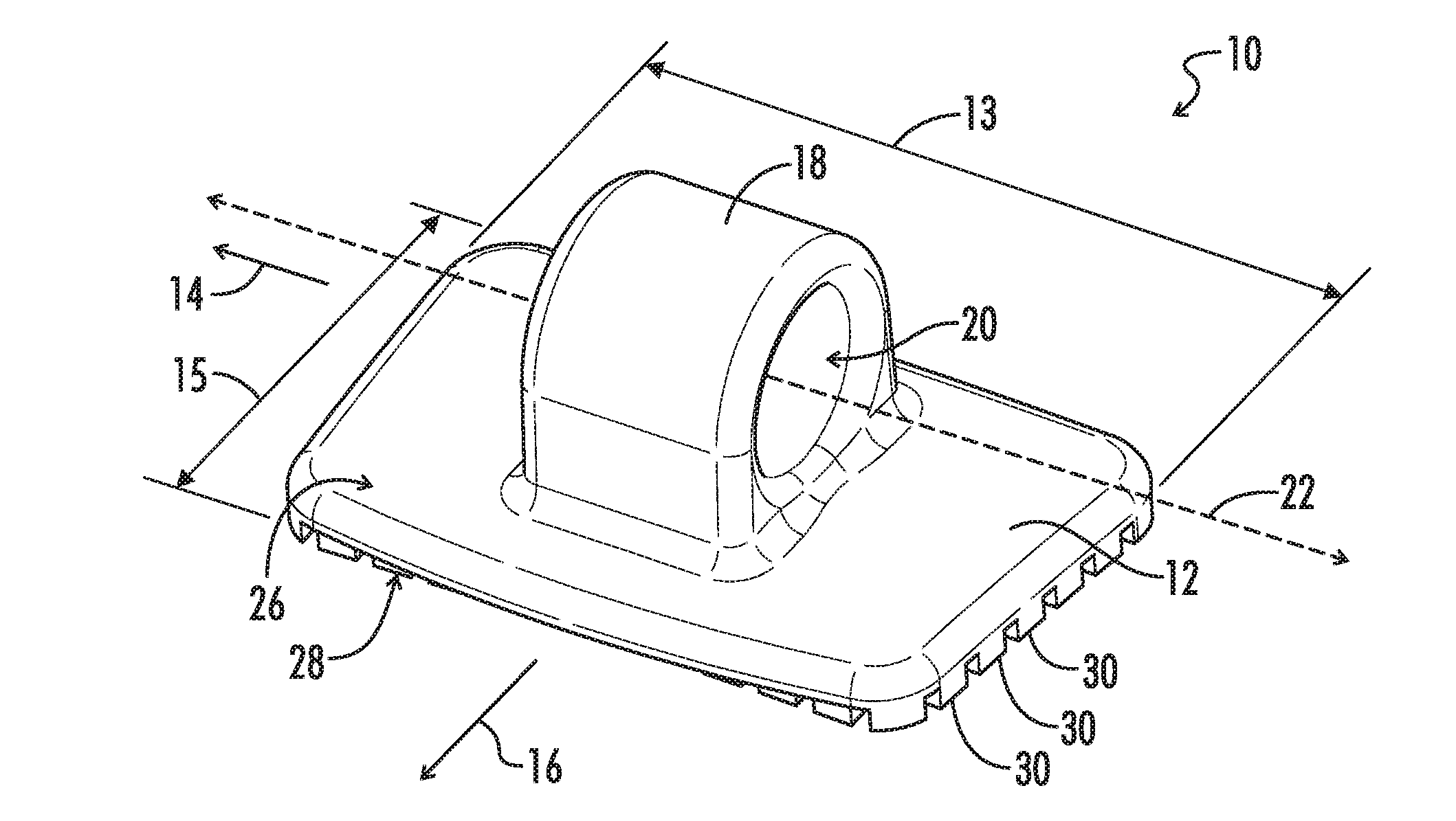
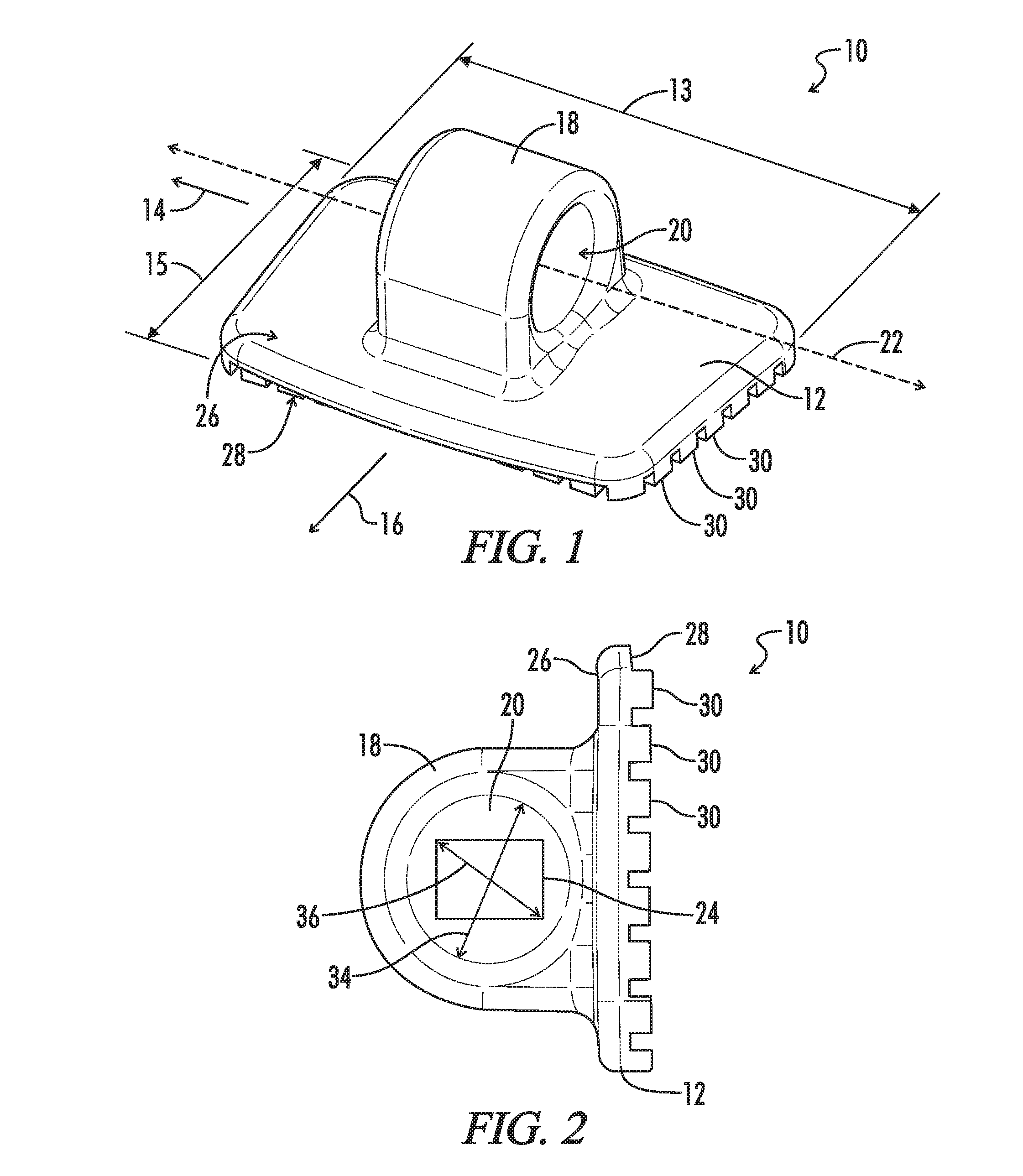
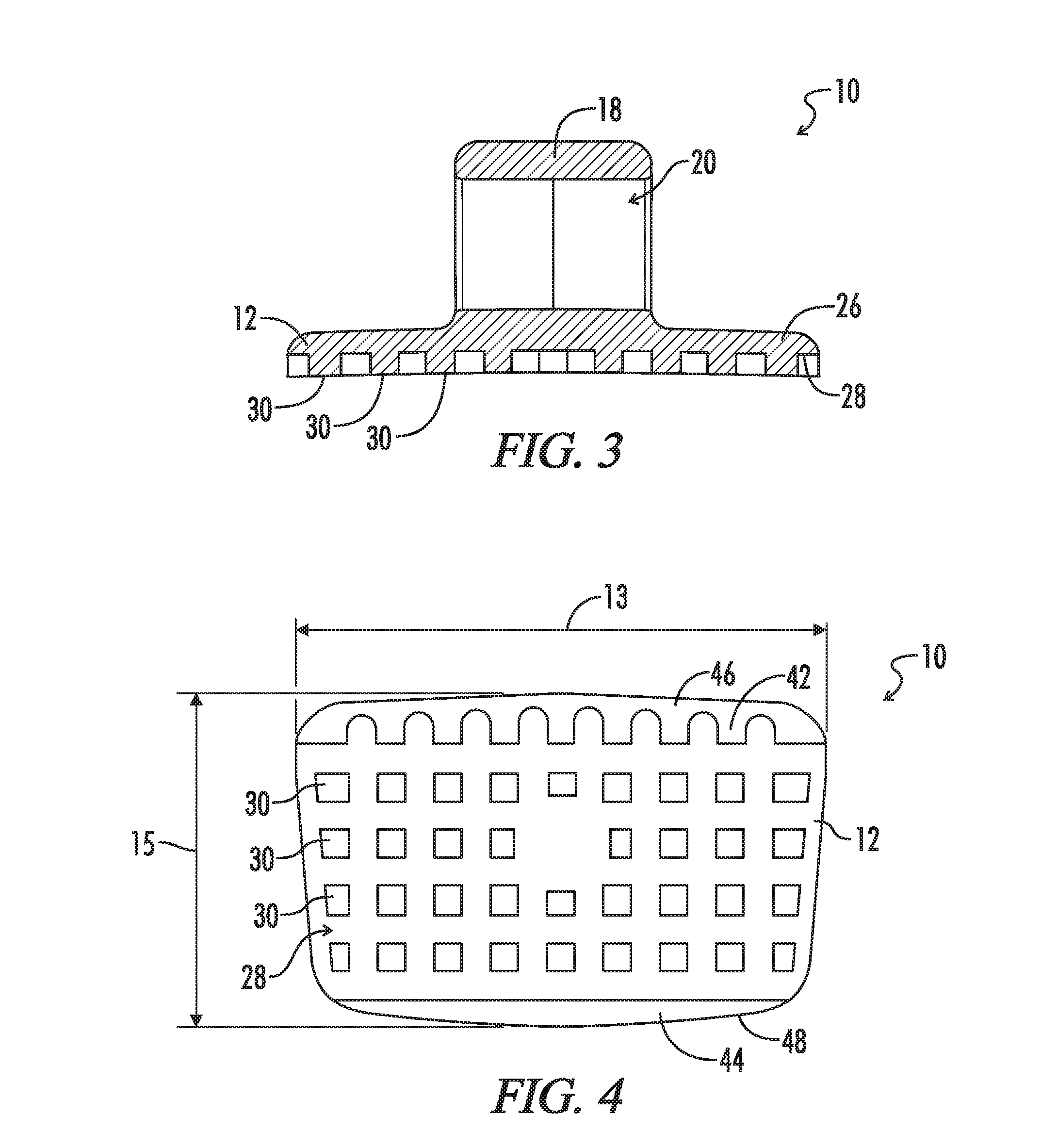
An orthodontic bracket for receiving an arch wire of orthodontic patients having both primary teeth and permanent teeth, the orthodontic bracket including a pad sized to fit on one of the primary teeth, the pad extending a first distance generally in a longitudinal direction and a second distance generally in a lateral direction, the first distance being greater than the second distance. An eyelet can extend from the pad, the eyelet including an aperture defined through the eyelet, the aperture having a central axis oriented transverse to the lateral direction. The aperture can slidingly receive the arch wire. A method including bonding the pad of the orthodontic bracket to one of the primary teeth of the patient.

Description

CROSS-REFERENCES TO RELATED APPLICATIONS[0001]This application is a non-provisional of U.S. Provisional Patent Application Ser. No. 62 / 140,419 filed Mar. 30, 2015 entitled Orthodontic Bracket and U.S. Provisional Patent Application Ser. No. 62 / 161,261 filed May 15, 2015 entitled Orthodontic Bracket For Primary Teeth, both of which are herein incorporated by reference in their entirety.[0002]A portion of the disclosure of this patent document contains material that is subject to copyright protection. The copyright owner has no objection to the reproduction of the patent document or the patent disclosure, as it appears in the U.S. Patent and Trademark Office patent file or records, but otherwise reserves all copyright rights whatsoever.STATEMENT REGARDING FEDERALLY SPONSORED RESEARCH OR DEVELOPMENT[0003]Not ApplicableREFERENCE TO SEQUENCE LISTING OR COMPUTER PROGRAM LISTING APPENDIX[0004]Not ApplicableBACKGROUND OF THE INVENTION[0005]The present disclosure relates generally to orthodo...

Claims


Application Information

Patent Timeline
IPC IPC(8): A61C7/28
CPCA61C7/282A61C7/18
Inventor BERNSTEIN, RAEL
Owner BERNSTEIN RAEL
Why Eureka
Try Eureka