Finishing face mill with reduced chip load variation and method of obtaining the same

a technology of chip load variation and face mill, which is applied in the direction of shaping cutters, metal working devices, manufacturing tools, etc., can solve the problems of dimensional error in the location of the face milled surface produced, large deleterious effect on surface roughness, and proportionate productivity drop

Inactive Publication Date: 2015-07-16
EIP HLDG
View PDF8 Cites 1 Cited by
  • Summary
  • Abstract
  • Description
  • Claims
  • Application Information

AI Technical Summary

Benefits of technology

[0010]In an example embodiment a face milling tool is provided including a body which is rotatable about an axis, at least one wiper tooth, and at least two primary cutting teeth mounted on the body having a cutting edge for cutting about the axis. The primary cutting teeth are staggered radially relative to each other by a r

Problems solved by technology

While the radial misalignments of the primary cutting teeth have a deleterious effect surface roughness by perturbing the widths of the feed grooves from their ideally equal widths, the axial misalignments of the primary cutting teeth have an even greater deleterious effect on surface roughness by also perturbing the depths of the feed grooves relative to their ideally equal depths.
Decreasing the feed per primary tooth, due to its squared effect on Ra, has the greater impact on decreasing/improving (making more smooth) the surface roughness, but, holding all other cutting conditions constant, such as spindle speed, this also results in a proportionate decrease in productivity.
Increasing the corner radius will result in a proportionate decrease/improvement in surface roughness, but it also tends to direct a larger per

Method used


Image

  • Finishing face mill with reduced chip load variation and method of obtaining the same
  • Finishing face mill with reduced chip load variation and method of obtaining the same
  • Finishing face mill with reduced chip load variation and method of obtaining the same

Examples


Embodiment Construction

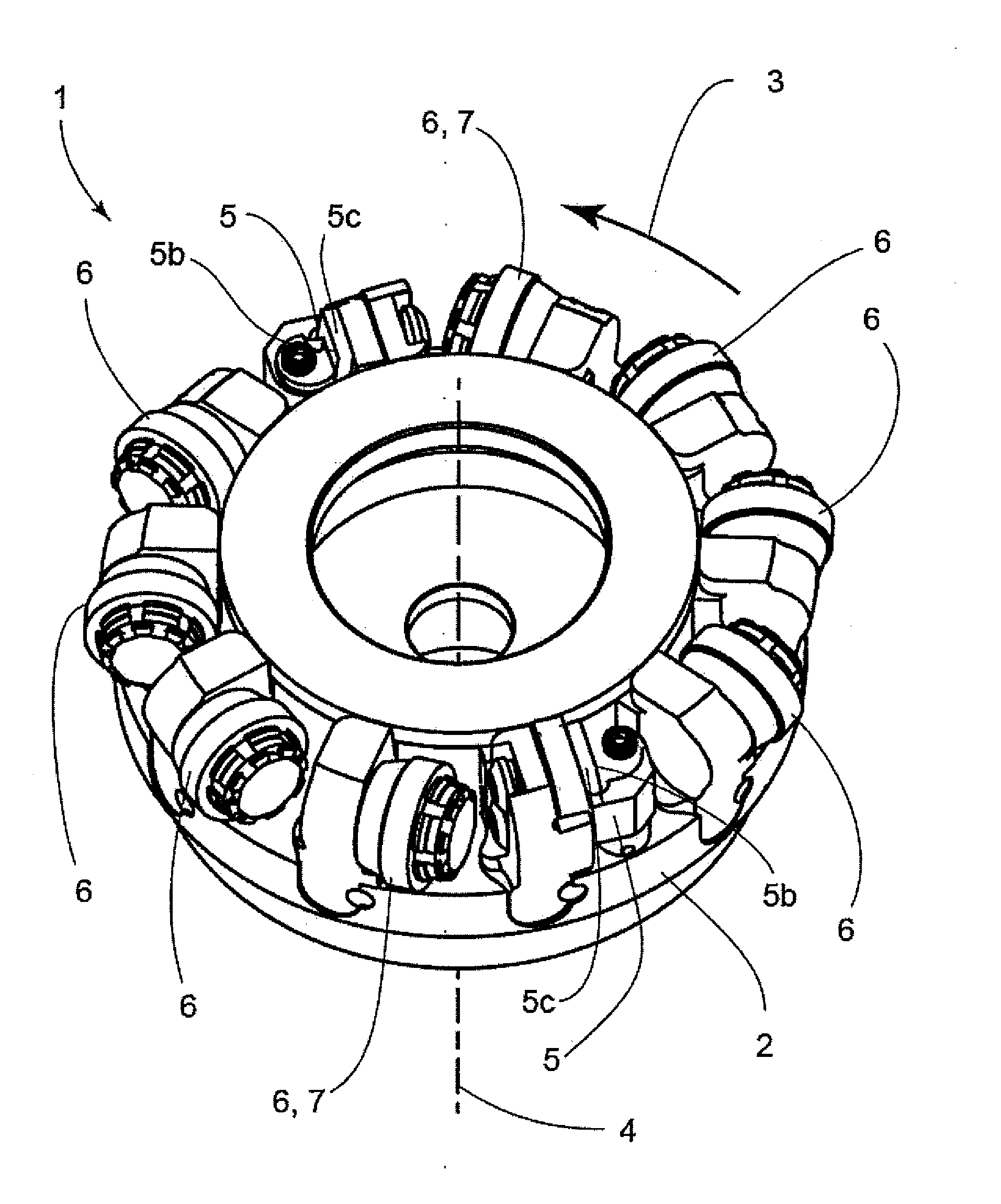
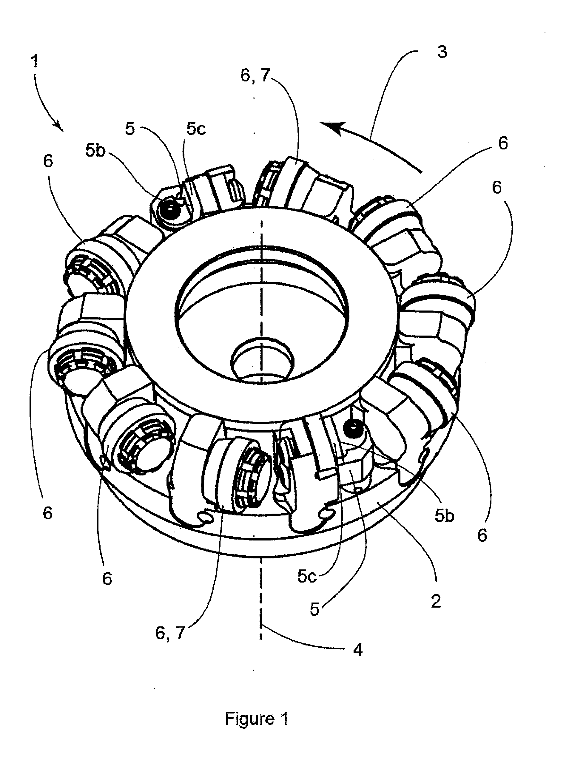
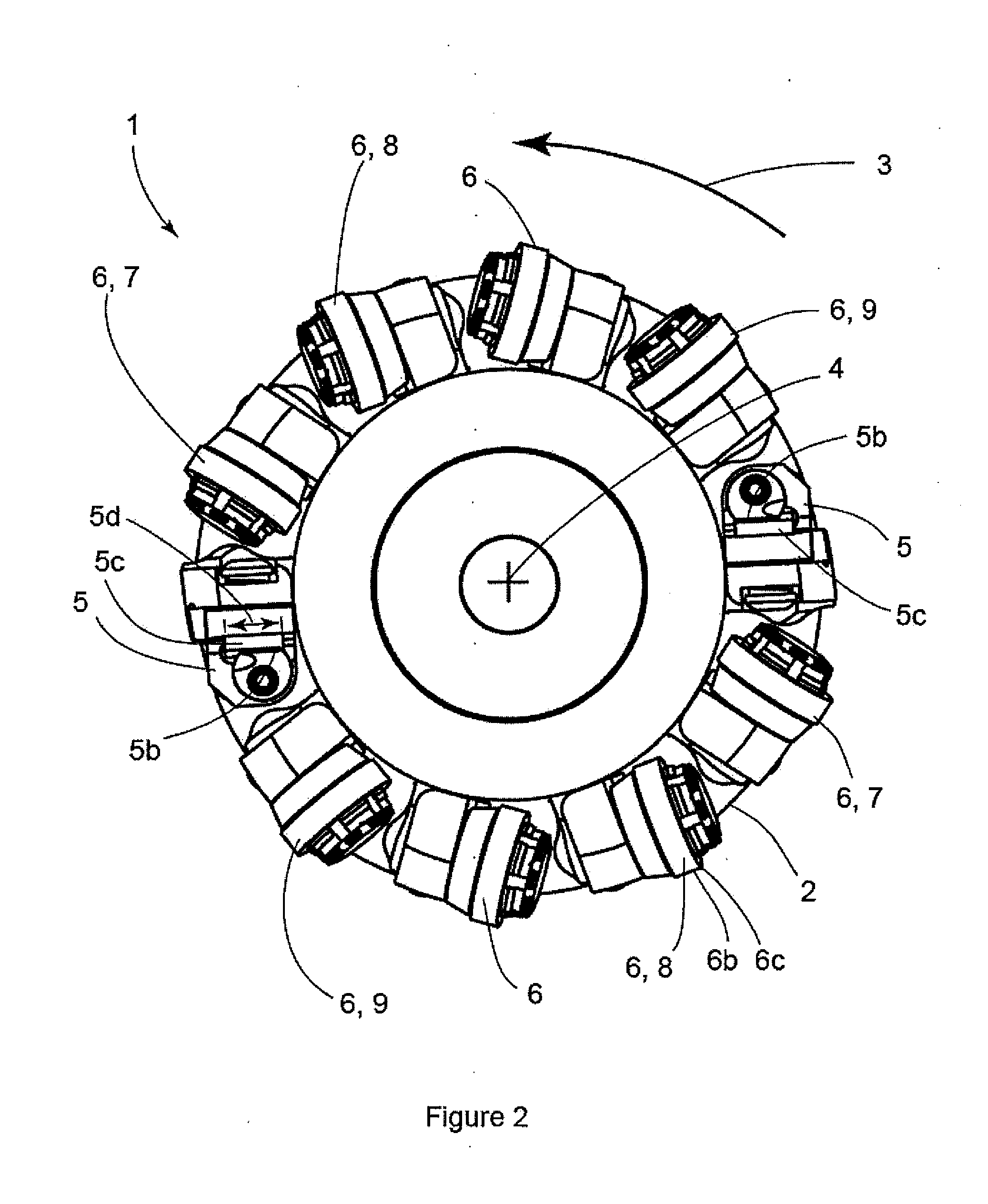
[0029]A finishing face mill 1 disclosed herein improves / decreases surface roughness. The present disclosure applies to any wiper-based finishing face mill, having a body 2 that is provided a rotating motion 3 about an axis 4 to provide a cutting motion, that incorporates, as shown in FIG. 1, its wiper teeth 5 (having cutting edge 5b) in place of primary cutting teeth 6 which results in a wiper-following primary cutting tooth 7, which is a primary cutting tooth that follows each replaced primary cutting tooth location where a wiper tooth has been placed, experiencing double the nominal chip load, fz, where fz=fn / zn, where fn is the feed per revolution and zn is the number of tooth locations on the cutter. It is described here with the assumption that tooth locations are evenly spaced circumferentially / angularly. Some face milling cutters have some departure from even spacing as a means of interrupting vibration regeneration that leads to instability and chatter, hence increasing the ...


PUM

PropertyMeasurementUnit
Lengthaaaaaaaaaa

Abstract

A face milling tool includes a body which is rotatable about an axis, at least one wiper tooth, and at least two primary cutting teeth mounted on the body having a cutting edge for cutting about the axis. The primary cutting teeth are staggered radially relative to each other by a radial shift so that a chip load variation during operation is less than 0.7 times a mean primary-tooth chip load. A method for determining the primary cutting tooth radial positions on a face milling tool body is provided such that a chip load variation during operation is less than 0.7 times a mean primary-tooth chip load.

Description

CROSS-REFERENCE TO RELATED APPLICATION[0001]This application is based upon and claims priority to U.S. Provisional Application Ser. No. 61 / 927,408, filed on Jan. 14, 2014, the content of which is fully incorporated herein by reference.BACKGROUND OF THE INVENTION[0002]A face milling tool, or face mill, has one or, more generally, multiple primary cutting teeth affixed to the face mill body around its circumference, generally substantially equally spaced, and aligned as best as possible to one another in both the axial and radial dimensions of the face mill. Each primary cutting tooth is generally made up of a replaceable cutting insert 6b (FIG. 2) and its provisions for attachment to the face mill body. Each insert 6b defines a cutting edge 6c that may be circular as shown in the illustrative examples here, or have a radiused tip where it forms the final surface. A face mill is operated by attaching it to the spindle of a machine tool. The spindle then rotates to produce a cutting mo...

Claims


Application Information

Patent Timeline
IPC IPC(8): B23C5/06B23C5/16
CPCB23C5/06B23C5/165B23C2250/00B23C2230/00B23C2210/28B23C2200/208B23C2210/282B23C2210/325B23C2220/28Y10T407/1908
Inventor ENDRES, WILLIAM J.WOODRUFF, DOUGLAS J.
Owner EIP HLDG
Why Eureka
Try Eureka