Compression Bandage

a compression bandage and bandage technology, applied in the field of compression bandages, can solve the problems of compressing the pad and reducing the absorbability of the pad, and achieve the effect of generating a compressive force on the wound and improving the design

Inactive Publication Date: 2016-10-06
JBC
View PDF4 Cites 5 Cited by
  • Summary
  • Abstract
  • Description
  • Claims
  • Application Information

AI Technical Summary

Benefits of technology

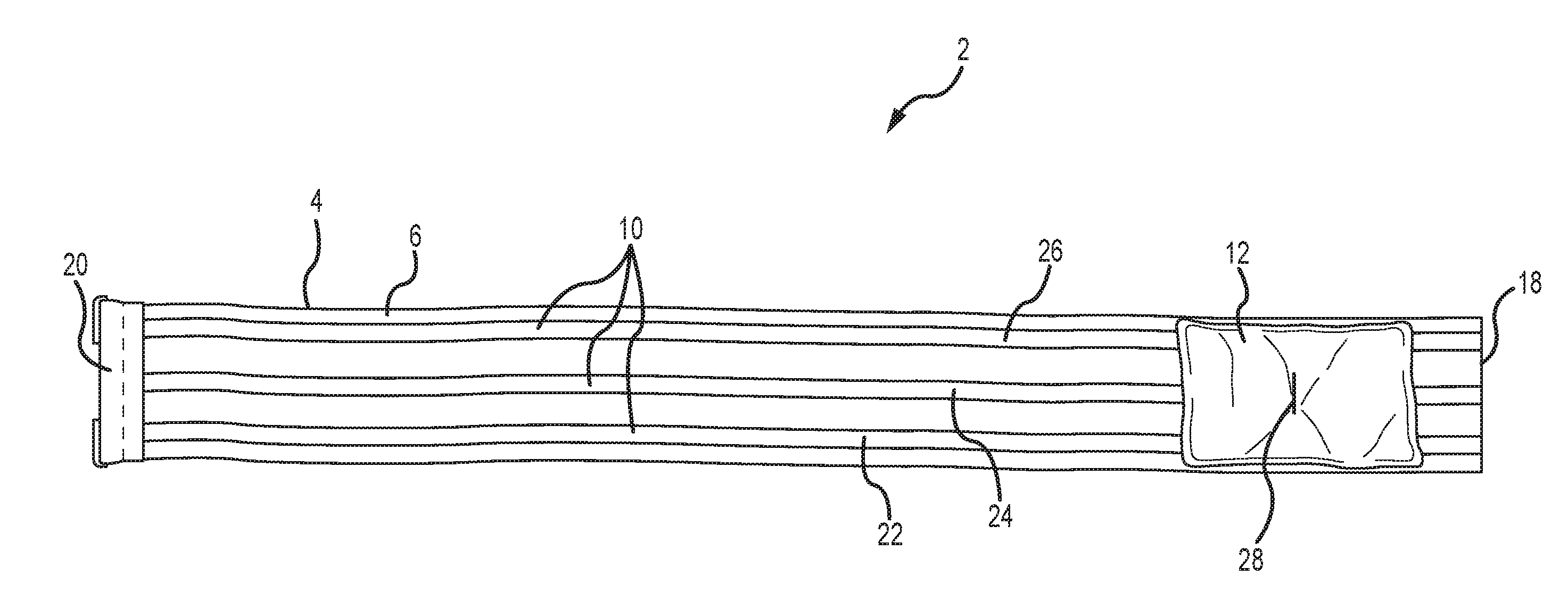
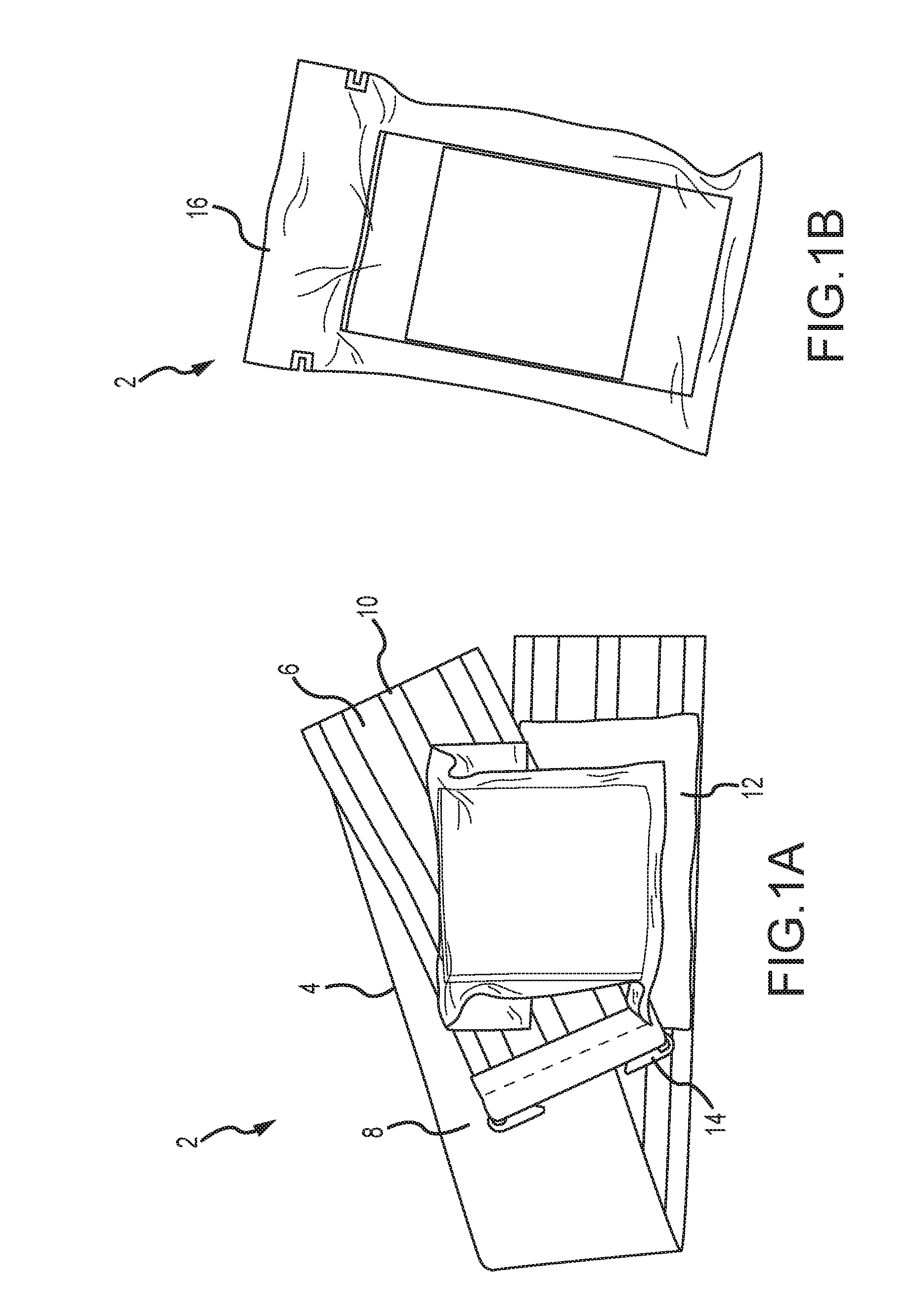
[0006]It is thus one aspect of embodiments of the present invention to provide a bandage with an improved design that can generate a compressive force on a wound. Specifically, it is an aspect of embodiments of the invention to provide a compression bandage with a raised retention element to help provide the compressive force on the wound, for example, to stem the flow of blood from the wound.
[0009]It is yet another aspect of embodiments of the invention to provide a compressive bandage wherein a pad is interconnected to a stretchable material at a central location. The pad is placed over a wound, and the pad provides absorbability. Prior art pads are interconnected to a strap or material around a perimeter of the pad, which compresses the pad and reduces the absorbability of the pad. In contrast, the central interconnection of the invention allows a greater area of the pad to remain uncompressed, which increases the pads ability to absorb fluid. This configuration also allows the pad to move relative to the stretchable material and remain over the wound.
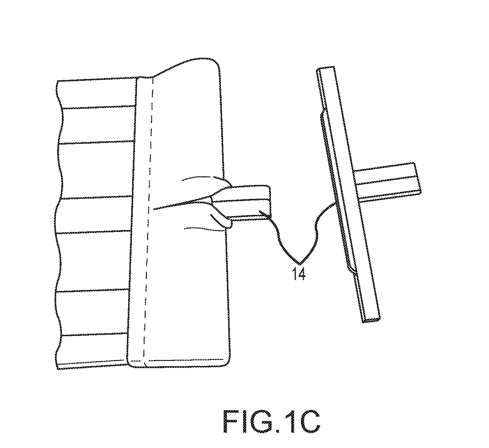
[0010]One particular embodiment of the invention is a compression bandage for treating an injury, comprising a stretchable material having a first end, a second end, and a first length between the first and the second ends when the stretchable material is in a relaxed state, the stretchable material having a second length between the first and second ends when the stretchable material is in a tensioned state, the second length being longer than the first length, the stretchable material also having a first side, a second side, and a first friction coefficient; a retention element disposed on the first side of the stretchable material, and the retention element raised above the first side, the raised retention element having a second friction coefficient, the second friction coefficient being greater than the first friction coefficient; a pad disposed on the first side of the stretchable material; and a securing fastener positioned proximate to the second end of the stretchable material, wherein the securing fastener is configured to hold the second end of the stretchable material in the tensioned state against the second side of the stretchable material such that the raised retention element contacts the second side of the stretchable material and prevents the second end of the stretchable material from slipping relative to the second side of the stretchable material.
[0016]Yet another particular embodiment of the invention is a compression bandage system for treating an injury, comprising a stretchable material having a first end, a second end, and a first length between the first and the second ends when the stretchable material is in a relaxed state, the stretchable material having a second length between the first and second ends when the stretchable material is in a tensioned state, the second length being longer than the first length, the stretchable material also having a first side, a second side, and a first friction coefficient; a plurality of raised retention elements disposed on the first side of the stretchable material, wherein the raised retention elements longitudinally extend between the first end and the second end of the stretchable material, and the raised retention elements are oriented substantially parallel to each other, wherein the raised retention elements each comprise a plurality of strands, wherein each strand forms a sinusoidal pattern as each strand extends from the first end to the second end of the stretchable material, the raised retention elements having a second friction coefficient, the second friction coefficient being greater than the first friction coefficient; a pad disposed on the first side of the stretchable material at a central location of the pad, and the pad proximate to the first end of the stretchable material; and a securing fastener positioned proximate to the second end of the stretchable material, wherein the securing fastener holds the second end of the stretchable material in place relative to the second side of the stretchable material such that the plurality of raised retention elements contacts the second side of the stretchable material and prevents the second end of the stretchable material from slipping relative to the second side of the stretchable material.

Problems solved by technology

Prior art pads are interconnected to a strap or material around a perimeter of the pad, which compresses the pad and reduces the absorbability of the pad.

Method used


Image

  • Compression Bandage
  • Compression Bandage
  • Compression Bandage

Examples


Embodiment Construction

[0030]The invention has significant benefits across a broad spectrum of endeavors. It is the Applicant's intent that this specification and the claims appended hereto be accorded a breadth in keeping with the scope and spirit of the invention being disclosed despite what might appear to be limiting language imposed by the requirements of referring to the specific examples disclosed. To acquaint persons skilled in the pertinent arts most closely related to the invention, a preferred embodiment that illustrates the best mode now contemplated for putting the invention into practice is described herein by, and with reference to, the annexed drawings that form a part of the specification. The exemplary embodiment is described in detail without attempting to describe all of the various forms and modifications in which the invention might be embodied. As such, the embodiments described herein are illustrative, and as will become apparent to those skilled in the arts, and may be modified in...


PUM


Abstract

A bandage with a raised retention element that generates a compressive force on a wound is provided. The bandage generally comprises a raised retention element disposed on an inner surface of a stretchable material. A pad may also be included on the inner surface of the stretchable material, and the pad may be placed over a wound. Then, a user may wrap the bandage around a portion of the injured person's body such that the stretchable material stretches and wraps upon itself. The raised retention element on the inner surface of the stretchable material has a higher coefficient of friction than the stretchable material, and thus, the raised retention element helps secure the bandage around the portion of the injured person's body to generate a compressive force on the wound.

Description

CROSS-REFERENCE TO RELATED APPLICATIONS[0001]This application claims priority under 35 U.S.C. §119(e) to U.S. Provisional Patent Application Ser. No. 62 / 141,920 filed Apr. 2, 2015, which is incorporated herein in its entirety by reference.FIELD OF THE INVENTION[0002]The invention generally relates to compression bandages for treating injuries, and more specifically, to compression bandages that retain the bandage in a predetermined location.BACKGROUND OF THE INVENTION[0003]Medical supplies are necessary for treating injuries sustained by military personnel, hikers, construction workers, loggers, and other persons subject to bodily injury. Depending on the type of injury, the treatment protocol may call for immediate pressure to a wound, for example, to stem the flow of blood from the wound.[0004]Prior art bandages rely on numerous components to apply pressure to a wound. Examples of these prior art device may be found in U.S. Pat. Nos. 5,628,723, 6,593,508, 7,490,634, and 7,600,540;...

Claims


Application Information

Patent Timeline
Patent Type & Authority Applications(United States)
IPC IPC(8): A61F13/64A61F13/62A61F13/02A61F13/56
CPCA61F13/64A61F13/56A61F2013/5672A61F13/0273A61F13/622A61F13/08
Inventor CAVOLT, BRIAN
Owner JBC
Why Eureka
Try Eureka