
Ink jet printer and ink jet head

a technology of ink jet printers and ink jet heads, applied in printing and other directions, can solve problems such as density unevenness in printed images

Active Publication Date: 2016-10-06
BROTHER KOGYO KK
View PDF5 Cites 9 Cited by
  • Summary
  • Abstract
  • Description
  • Claims
  • Application Information

AI Technical Summary

Benefits of technology

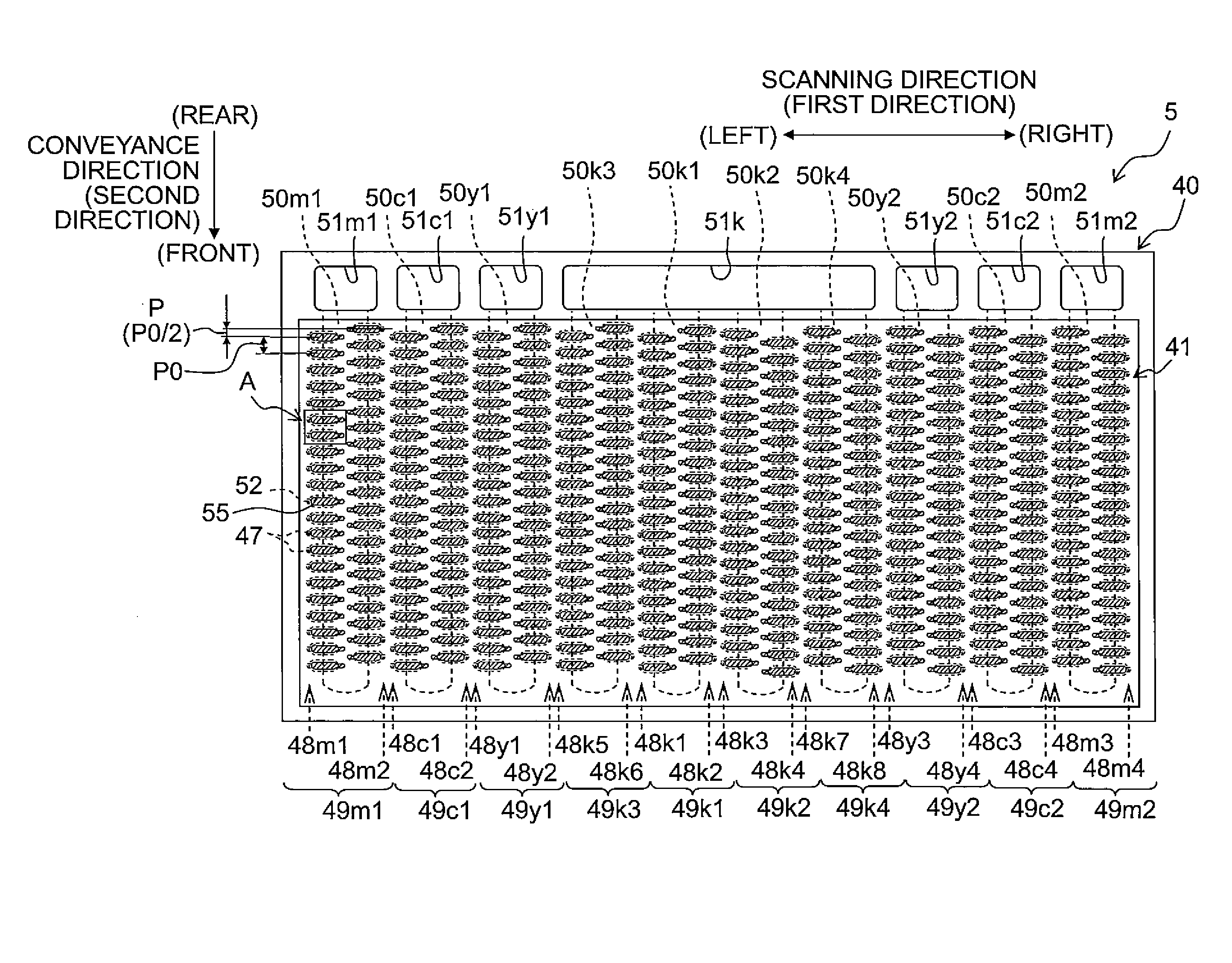
The patent aims to reduce the difference in the amount of ink jetted between nozzle groups that differ in jet frequency. The invention suggests arranging the third nozzle groups separately in the first direction and interposing them between the first and second nozzle groups. This arrangement helps to reduce the difference in ink temperature between the second and third nozzle groups when starting the second printing process, resulting in less density unevenness in images.

Problems solved by technology

This difference in the ink jet amount causes density unevenness to occur in printed images.

Method used


Image

  • Ink jet printer and ink jet head
  • Ink jet printer and ink jet head
  • Ink jet printer and ink jet head

Examples


first embodiment

[0044]Next, a first embodiment of the present teaching will be explained.

[0045](A Schematic Configuration of a Printer)

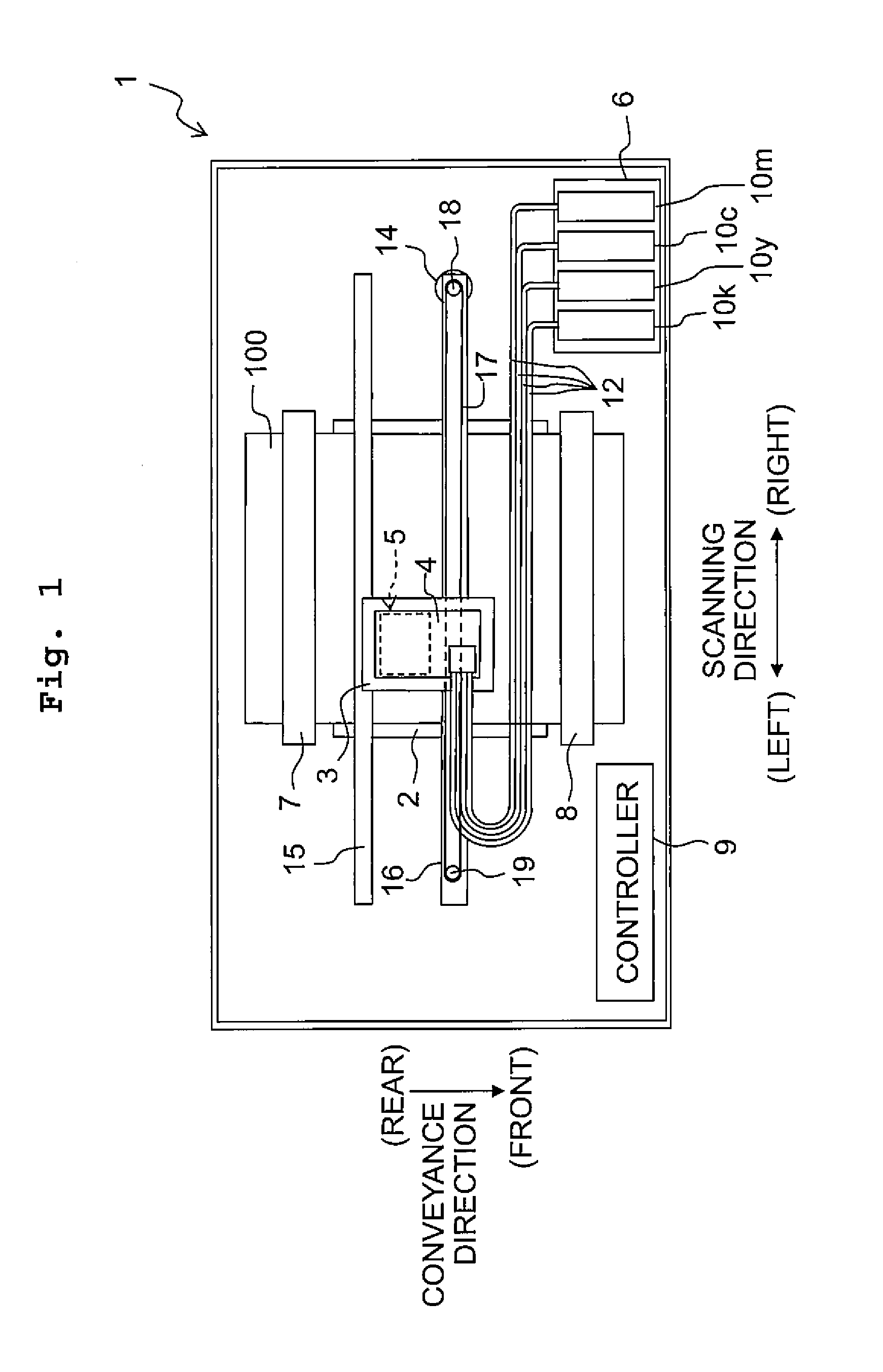
[0046]As depicted in FIG. 1, a printer 1 includes a platen 2, a carriage 3, a sub-tank 4, an ink jet head 5, a holder 6, a paper feed roller 7, a paper discharge roller 8, a controller 9, and the like. Further, hereinbelow, the near side of the page of FIG. 1 will be defined as “upper side” or “upside” of the printer 1 while the far side of the page will be defined as “lower side” or “downside” of the printer 1. Further, the front-rear direction and left-right direction depicted in FIG. 1 are defined as the “front-rear direction” and “left-right direction” of the printer 1, respectively.

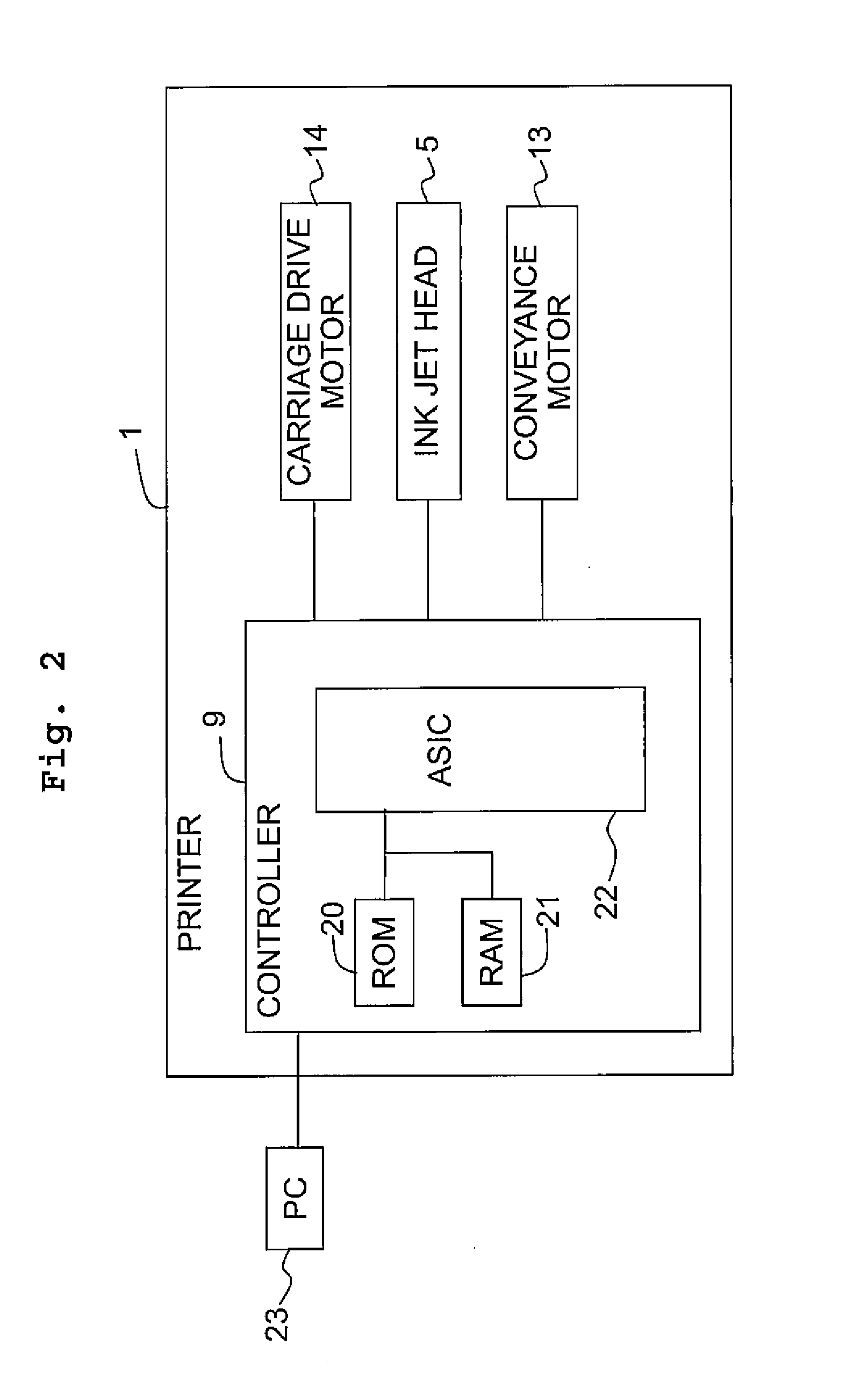
[0047]On the upper surface of the platen 2, there is carried a sheet of recording paper 100 which is a recording medium, Further, two guide rails 15 and 16 are provided above the platen 2 to extend parallel to the left-right direction of FIG. 1 (to be also referred to as a scanning d...

second embodiment

[0109]Next, a second embodiment of the present teaching will be explained. As with the first embodiment, the second embodiment is also an example of applying the present teaching to a printer having a serial ink jet head moving in the scanning direction. While the printer in the second embodiment is different in configuration of the ink jet head from the printer in the first embodiment, the other configurations are all the same. Therefore, the same reference signs are assigned to the components other than the ink jet head as those in the first embodiment, and any explanation therefor will be omitted.

[0110]As depicted in FIG. 12, an ink jet head 65 includes five head units 61 aligning in the scanning direction, and a holding member 60 holding the five head units 61. The five head units 61 have the same structure. That is, the five head units 61 have the same outer shape, the same shape of their inner ink channels, and the like.

[0111]Each of the head units 61 has a channel unit 62, an...

first modification

[0123]As with an ink jet head 65A depicted in FIG. 13, less amount of dislocation P′ than P / 4 may be applied to the second head unit 61b and the third head unit 61c with respect to the first head unit 61a.


PUM


Abstract

There is provided an ink jet primer including a carriage, and an ink jet head. The ink jet head has two first nozzle groups to jet a first ink, two second nozzle groups to jet a second ink, and two third nozzle groups to jet the second ink. Each of the first, second and third nozzle groups includes a plurality of nozzles arrayed at a pitch P along a second direction. The second nozzle groups accord respectively with the first nozzle groups in terms of nozzle position in the second direction, the third nozzle groups are dislocated respectively from the second nozzle groups in terms of nozzle position in the second direction, and any two groups selected from the first and second nozzle groups are arranged respectively on two opposite sides of each of the third nozzle groups in the first direction.

Description

CROSS REFERENCE TO RELATED APPLICATION[0001]The present application claims priority from Japanese Patent Application No. 2015-073701, filed on Mar. 31, 2015, the disclosure of which is incorporated herein by reference in its entirety.FIELD OF THE INVENTION[0002]The present invention relates to ink jet printers and ink jet heads.DESCRIPTION OF THE RELATED ART[0003]Conventionally, there are known ink jet printers applying such a method as to print image and the like by jetting ink from respective nozzles toward a recording medium while moving an ink jet head having the plurality of nozzles in a predetermined scanning direction. There are known ink jet heads used in such ink jet printers to have four types of nozzle rows jetting inks of four colors: black (K), cyan (C), magenta (M), and yellow (Y). For example, two nozzle rows are provided for the ink of one color such that there are eight nozzle rows in total for the four colors.[0004]Further, there is known an ink jet head in which t...

Claims


Application Information

Patent Timeline
IPC IPC(8): B41J2/145
CPCB41J2/145B41J2/04551B41J2/21B41J2/14209B41J2/5056B41J2/51B41J2002/14225B41J2002/14459
Inventor KOIDE, SHOHEIITO, ATSUSHI
Owner BROTHER KOGYO KK
Learn More