
Cell Culture Array System For Automated Assays And Methods Of Operation And Manufacture

a cell culture array and automated assay technology, applied in the field of handling, can solve the problems of particularly challenging mammalian cell culture, and achieve the effect of eliminating tubing and connectors

Active Publication Date: 2016-10-06
EMD MILLIPORE CORP
View PDF0 Cites 12 Cited by
  • Summary
  • Abstract
  • Description
  • Claims
  • Application Information

AI Technical Summary

Benefits of technology

The invention is a new kind of microfluidic plate that eliminates the need for tubing and connectors and allows for long-term continuous perfusion cell culture using a passive gravity-driven flow. The plate also has direct analysis and cellular observation wells, making it easy to analyze and observe cells in real-time.

Problems solved by technology

Mammalian cell culture is particularly challenging, particularly for maintaining effective solid aggregates of cells in culture.

Method used


Image

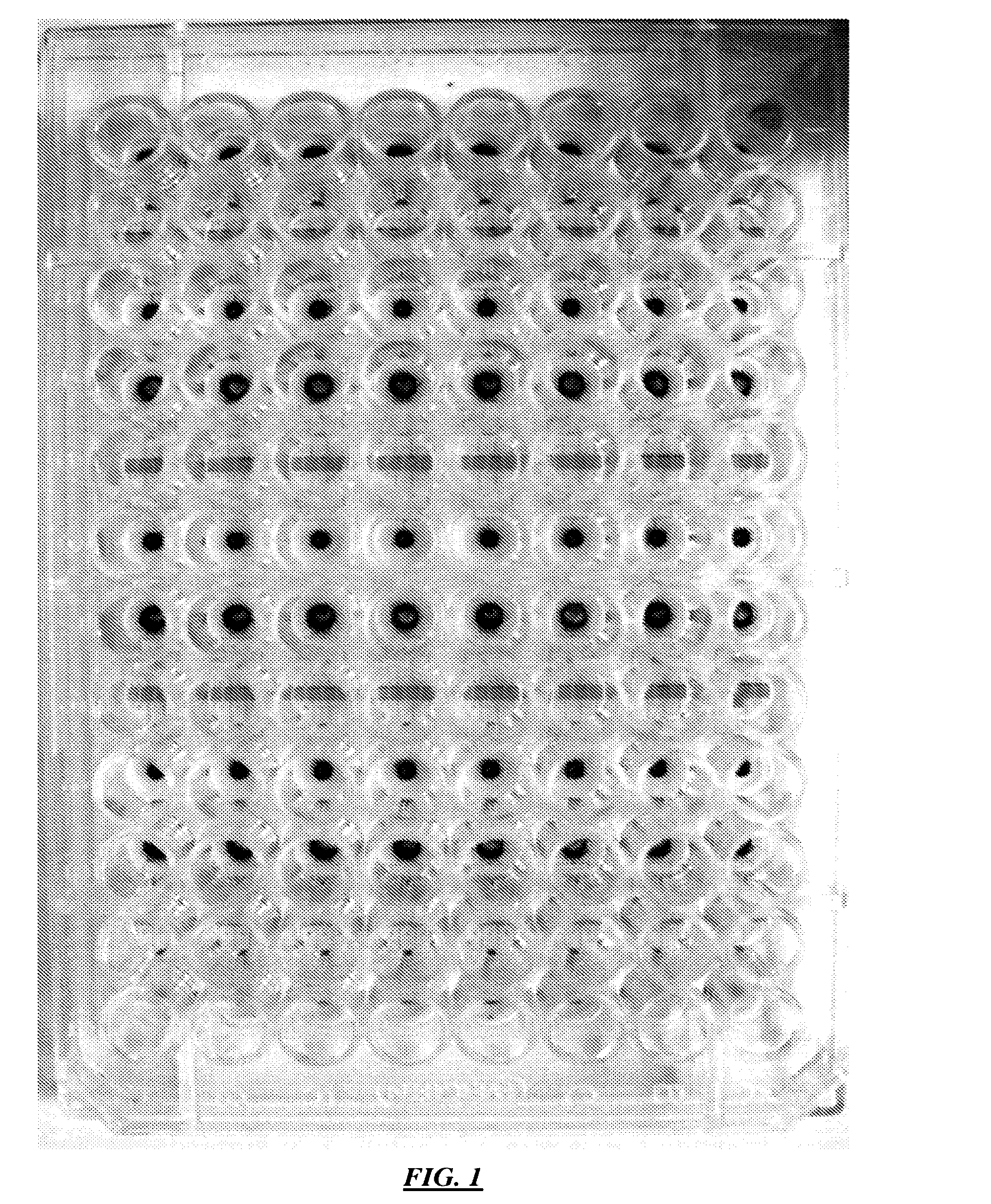
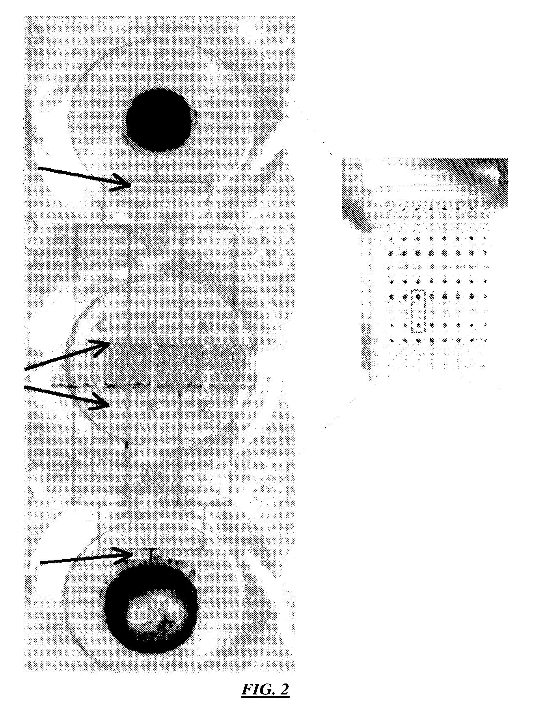
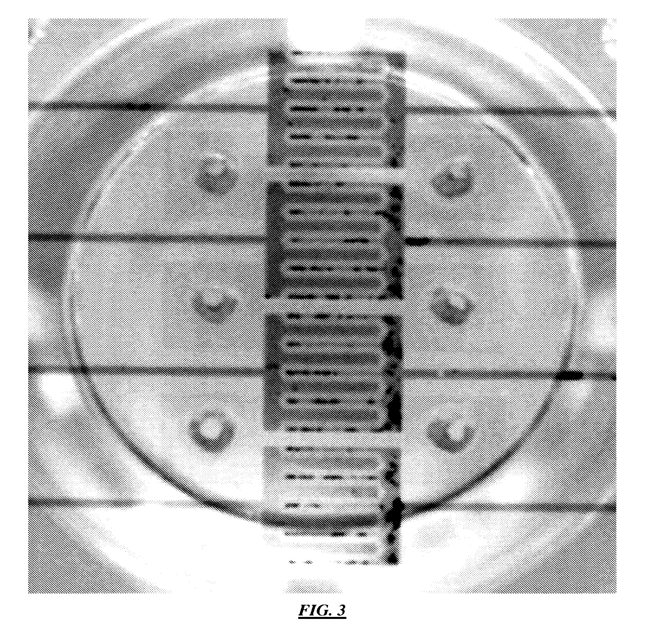
  • Cell Culture Array System For Automated Assays And Methods Of Operation And Manufacture
  • Cell Culture Array System For Automated Assays And Methods Of Operation And Manufacture
  • Cell Culture Array System For Automated Assays And Methods Of Operation And Manufacture

Examples


example 1

5. Example 1

[0162]FIG. 30 is a block diagram illustrating two components of a direct soft molding process according to specific embodiments of the invention. The two components illustrated are: (1) An injection molded top piece made of acrylic containing at least alignment marks (to be assembled to the microfluidic mold) and well structures generally complying with standard microtiter plate formats. (Alternatively, a standard well plate may be used.) (2) A microfluidic mold fabricated using semiconductor technologies on a 6″ silicon wafer containing the microfluidic cell culture arrays made of epoxy or electroplated metals, as well as the alignment marks so the well structures aligned to the microfluidic structures during the molding process. An injection molded top piece is made of acrylic or any similar suitable material and contains well structures that preferably comply with standard microtiter plate formats as will be discussed more herein. On the right is shown a microfluidic ...

example 2

6. Example 2

[0170]FIG. 32A-C illustrate three components of a direct soft molding process according to specific embodiments of the invention. In the figure, (A) shows an injection molded top piece that includes well structures complying with standard microtiter plate formats. As discussed above, rather than the injection molded top piece shown, a standard microtiter plate may be used as the top piece that includes well structures complying with standard microtiter plate formats, (B) Illustrates a 1.5 mm thick acrylic circular sheet (6″ in diameter), and (C) illustrates a microfluidic mold fabricated on a 6″ silicon wafer containing microfluidic cell culture units (in this example 8×4 units) in an arrays made of epoxy, etched silicon, or electroplated metals, as well as a spacer to control the minimum thickness of the soft polymer after molding. The mold is coated with fluoropolymer to reduce stiction of the soft polymer to the mold. As shown in the figure, the microfluidic mold is g...


PUM


Abstract

A number of novel improved microfluidic configurations and systems and methods of manufacture and operation. In one embodiment, three wells are used for independent cell culture systems in a cell culture array. In a second aspect, artificial sinusoids with artificial epithelial barriers are provided with just one (optionally shared or multiplexed) fluidic inlet and one (optionally shared or multiplexed) fluidic output, where the medium output also functions as a cellular input. A pneumatic cell loader combined with other components provides a fully automated cell culture system. Magnetic alignment of plate molds provides advantages and ease of molded manufacture.

Description

CROSS REFERENCE TO RELATED APPLICATIONS[0001]This application is a continuation of U.S. patent application Ser. No. 12 / 348,907 filed Jan. 5, 2009, which claims priority from provisional patent application 61 / 037,297 filed Mar. 17, 2008 and from 61 / 018,882 filed Jan. 3, 2008, each incorporated herein by reference.[0002]This application discusses technology related to U.S. Ser. No. 11 / 994,997, filed Aug. 11, 2008, which is a National Stage Entry of PCT / US06 / 26364, filed Jul. 6, 2006 and which claims priority from provisional patent application 60 / 773,467 filed 14 Feb. 2006 and from provisional patent application 60 / 697,449 filed 7 Jul. 2005.[0003]This application discusses technology related to U.S. application Ser. No. 12 / 019,857, filed Jan. 25, 2008, which claims priority to U.S. Provisional Patent Application No. 60 / 900,651 filed on Feb. 8, 2007.[0004]This application discusses technology related to U.S. application Ser. No. 11 / 648,207, filed Dec. 29, 2006, which claims priority to...

Claims


Application Information

Patent Timeline
Patent Type & Authority Applications(United States)
IPC IPC(8): C12M3/06G01N35/00C12M1/36B01L3/00C12M1/00C12M1/32
CPCC12M23/16G01N2035/00148C12M23/12C12M41/48B01L3/502715B01L3/502761B01L3/50273G01N35/0099G01N35/00029B01L2300/0829B01L2300/0848B01L2300/0861B01L2400/0487B01L2400/0457C12M29/10B01L3/5025B01L3/5027
Inventor HUNG, PAUL J.LEE, PHILLIP J.
Owner EMD MILLIPORE CORP
Learn More